What's new
What's new

machining keyway in 8" bore

Last place I worked had a 21” stroke “ Butler “ slotter for jobs like that. I think “ Butler “ also did a monster slotter that would do a 36” stroke.

Regards Tyrone.

That would be ideal, but also might not fit under his roof. Or through his door. Or get used for anything else ever again... Lol. Awesome machines though. We used to have a couple where I served my apprenticeship, fun to run, really quiet. Like running a shaper stood up on end, with a built in cross-slide rotary table. We had a couple frequent jobs on them for the big steel mills - main drive couplings - they had a female fit that was basically a square with round ends. The mating piece was just a large shaft (around 30" diameter) with two flats milled down at 180°.
 
Seems to me you could mount your cutter on a long bar between centers on a lathe. Fixture your bushing on the carriage. Carriage traverse with power feed. if your spindle center must revolve for feed to work, use a live center in the spindle end.
 
What would the clapper look like that carries a 4" bar 24" long?

You could probably do it in a Maag, but buying a 15 meter gear shaper to do this one job might be overkill :D

edit: Eek, I underestimated the stroke on late-models (1980 is late model to me.) You could do it on a mere 2 1/2 meter machine.

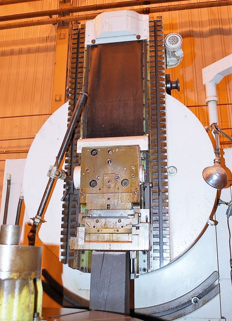
Clapper box and ballscrew-driven slide 26" stroke (plus clearance)

20851b.jpg


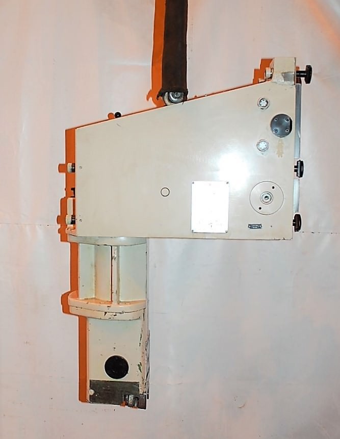
internal extension

20851i.jpg


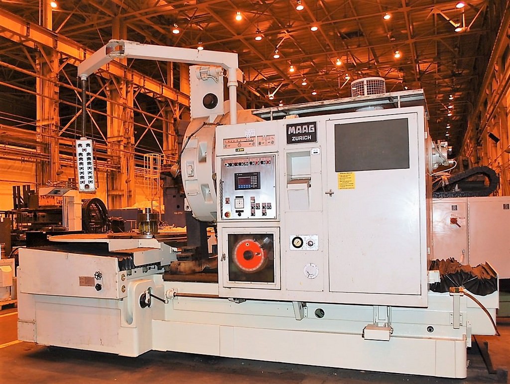
and the entire machine for scale (table will mount a 100" blank)

20851d.jpg


So maybe not as impractical as I thought !
 
I have some flex-connected couplings in cast iron with a roughly 4.5" bore. Each weighs around 100lbs, so I do a two-man lift when handling them. I suspect the coupling you speak of is about 1K lbs or more?

Yeah...a little more. At a guess probably around 6,000-8,000 pounds. IIRC they coupled a 5,000 horsepower drive motor.
 
Butler slotter is what we had in work, blind hole slots were a pig, you had to undercut the bottom of the bore, occasionally it drill from the back foot the chips otherwise they pack, you then plug welded the hole but the last one I just screwed a plug in, which turned out to be handy as a bolt in the hole could push the shaft out, saved a puller job.
There was another slotter with a rotary table that I can’t remember the name Landis comes to mind but the all had 24 or 30 inch stroke, the smallest was a ass end slotter on a mill ( now in my shop) I think it’s 4”, the most useful slotter in the shop in my opinion.
I think enerpac did a hydraulic gizmo for keyways, slow but sure.
Mark
 
Shapers,slotters, and planers were common machines back then.

What would the clapper look like that carries a 4" bar 24" long?

We have bars for our planer and the clapper box is mounted out on the end of the bar. I think the longest bar is about 35" long. We cut a long keyway like that one time and then the customer had the part heat treated and the keyway got tighter. It was too hard to cut so I had to mount a grinder on the end of the bar and grind the keyway out to size on the planer. FUN FUN
 
These parts are just spacers for a steel mill. The keyway just has to slide over an 1 1/4" key. Im just guessing but I think these are for a slitter in a tube mill. Its kind of like a rotary shear that cuts the coils down to the proper width to make steel tubing. They are sort of like giant spacers like the ones on a horizontal milling machine arbor.
 
Pinion gear/spindle gear-driven or chain-driven slot milling arbor?? The pinion and spindle gears from a 9" grinder would have enough size to do the job I think. The chain would have more heavy-load capacity and probably would be more suitable. I suppose that is crazy thinking. But with an 8" bore there is quite a bit of real estate available. Is such a device made for a similar open operation rather than for use in a bore?

I won't be offended if you play the laugh tape. Just thinking out loud.

If it were feasible, seeing some nice fat chips coming off the cutter would be pretty sweet and the process would be pretty fast.

Denis
 
If it's just clearance and these are just a spacer, why not make a plug and drill a 2" hole half in each piece ? Could get quite a few shots out of one plug by rotating it.

That would probably work but the customer wants a 1 5/16 keyway. Plus these are not real thick by the time you get the keyway in there. They want the keyway .790" deep
 
If it is just a spacer and does not transmit torque how about a two piece construction. An outer sleeve and a inner sleeve with the slot pressed together.

Tom
 
If it is just a spacer and does not transmit torque how about a two piece construction. An outer sleeve and a inner sleeve with the slot pressed together.

Tom

Now that is one good idea! Adding a bit of a proper Loctite (609?) should “seal the deal.”

Cut outer ring, press in split ring with Loctite, finish bore the split ring.

Denis

Added: Cutting the split ring could itself present a challenge holding it while cutting the segment out as the pipe will tend to collapse once the segment is out. I think I would do that with a suitable piece of pipe slid just snuggly over a solid mandrel. The mandrel would have a notch cut in it corresponding to the segment to be cut out of the pipe. The seam of the pipe would slide over the notched part of the mandrel if seamless pipe were not used. Once the notch was cut in the pipe and the pipe was "death groipping" the mandrel the mandrel could be pressed out of the cut pipe. Or, it would be practical and quicker to drive wedges to spring the pipe open allowing the mandrel to be removed.

One other way to machine the notch out of the pipe (and maybe better) would be to cut the pipe a half inch long and tack weld it to a bracket on each end suitable for holding the pipe. Cut the notch and then cut off the brackets. Press the split ring into the outer pipe and face the ends of the pipe and split ring.
 
You can have all the good ideas you like, but the customer supplies the print and the machine shop doesn't just get to make arbitrary changes to design when they feel like it because "it would be a good/cool idea..." or be an easier way to make a similar part. Especially on steel mill parts or other similar things where serious power might be transmitted. Those kinds of things are designed and checked by an engineer for sufficient strength and safety margin. Doing otherwise could leave you open to potentially company-ending liability if the part failed and someone got hurt or the production line was shut down and the mill lost their income stream. I know a lot of you guys know better than that.


Back
Top