What's new
What's new

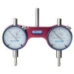
Made a spindle tram tool on the Bridgeport this weekend

CompositesGuy

Aluminum
Joined
May 30, 2009
Location
AZ
I got a couple of matching dial indicators off Ebay and finally got around to making a spindle tram tool. I used hardened 15-5ph stainless for the body, and an off-the-shelf hardened & ground 416 stainless pin for the shaft. Kept everything close tolerance and reamed the holes. As a final operation I cut the bottom flat surface parallel to the axis of shaft rotation, by mounting the assembled shaft/body in a collet on the lathe and taking a skim cut. The indicators were carefully set into the body (using feeler gauges between the dial and the body) at a height such that, when the tool is set onto a surface plate both needles point straight up to zero. The ground shaft is 0.75" diameter, because my 3/4" collet seems to live in my Bridgeport most of the time.

Reading some other threads about this type of tool I think that some have missed the fact that the tool can operate in two modes. I call them "coarse" and "fine". For the coarse mode you set the tool upright on a surface plate, and then zero both indicators. Then you put the tool into the mill and tilt the head until both indicators are in contact with the table and read the same value. I did this several times, and got the head to within 0.0005" of tram every time... much faster than I could with an Indicol and my Starrett Last Word. This method basically aligns the bottom of the tram tool to the table, but that is "coarse" because the shaft of the tool and R8 collet may be tilted within the spindle a little bit. In other words, even if the tool is made perfectly, the axis of the tram tool shaft may be slightly tilted from the true axis of spindle rotation thanks to tilt of the collet. That's ok though, because you still have "fine" mode. In this mode, you mount the tram tool in the mill, bring the tool into contact with the table, and zero the indicator on the left. Then you spin the tool 180 degrees about the spindle axis and zero the other indicator on the same spot on the table. Then you return the tool to is original position (back 180 degrees) and look at the needles. If both needles are on zero at that point, you are done. More likely, the first indicator will be zero and the other something like .0005". Then you just tilt the head until you split the difference (.00025) on both dials. Thus, "fine" mode removes the inaccuracy introduced by how carefully the tram tool was made, and also removes the aforementioned effect of the R8 collet tilting within the spindle.

(Note: In the picture, I touched the tool to the top of my vice jaws, which are not perfectly aligned to the table. Hence the slight difference between indicators).
 

Attachments

  • SpindleTram.jpg
    SpindleTram.jpg
    222.2 KB · Views: 100
Last edited:
Not to long ago I wrote up a issue with caliper needles not getting close when in between .001 marks. That was with Mitutoyo and Starrett.
You reminded me to make one of these tools but use the same two indicator brand and model.

The alternative is to use a rod and swing a single indicator 180 degrees, back and forth. Those circular arcs drawn on nice shinny mill tables.
If people would only lift the point up first before rotation.
 
If you do an "advance search" on Ebay you can view listings for which there are 2 or more items available. That's how I found these indicators.
 
The alternative is to use a rod and swing a single indicator 180 degrees, back and forth. Those circular arcs drawn on nice shinny mill tables.
If people would only lift the point up first before rotation.
The solution to that is to buy a ventilated front disk brake rotor. Doesn't matter what car it's for, just get one that's about the diameter you want. Then use that to run the indicator around.

New, they're flat and parallel to better than a tenth.
 
The solution to that is to buy a ventilated front disk brake rotor. Doesn't matter what car it's for, just get one that's about the diameter you want. Then use that to run the indicator around.

New, they're flat and parallel to better than a tenth.
So much BS just to tram a quill, it's just not that complicated. Extend your quill all the way, put a angle plate on the table and against the quill, a light behind the quill makes it obvious If it is not square. This will get it within a thousandth, put 1 indicator on a arm and sweep around a 8" or so diameter roller bearing race. A 0 reading on the indicator and the head will be as square as it is possible to get it.
 
Did you check the run out on the R8 collet and shaft? The real check is fly cutting a piece of material.
That is why I use the single indicator on a arm Runout has no effect on this measurement To prevent damage on the indicater I make it being lifted just about 0.5mm or lessThat way you can rotate it without the need to lift it
Every measurement has a uncertainty it it Every item you ad to the measurement makes that uncertainty bigger
Peter
 
Last edited:
I got a couple of matching dial indicators off Ebay and finally got around to making a spindle tram tool. I used hardened 15-5ph stainless for the body, and an off-the-shelf hardened & ground 416 stainless pin for the shaft. Kept everything close tolerance and reamed the holes. As a final operation I cut the bottom flat surface parallel to the axis of shaft rotation, by mounting the assembled shaft/body in a collet on the lathe and taking a skim cut. The indicators were carefully set into the body (using feeler gauges between the dial and the body) at a height such that, when the tool is set onto a surface plate both needles point straight up to zero. The ground shaft is 0.75" diameter, because my 3/4" collet seems to live in my Bridgeport most of the time.

Reading some other threads about this type of tool I think that some have missed the fact that the tool can operate in two modes. I call them "coarse" and "fine". For the coarse mode you set the tool upright on a surface plate, and then zero both indicators. Then you put the tool into the mill and tilt the head until both indicators are in contact with the table and read the same value. I did this several times, and got the head to within 0.0005" of tram every time... much faster than I could with an Indicol and my Starrett Last Word. This method basically aligns the bottom of the tram tool to the table, but that is "coarse" because the shaft of the tool and R8 collet may be tilted within the spindle a little bit. In other words, even if the tool is made perfectly, the axis of the tram tool shaft may be slightly tilted from the true axis of spindle rotation thanks to tilt of the collet. That's ok though, because you still have "fine" mode. In this mode, you mount the tram tool in the mill, bring the tool into contact with the table, and zero the indicator on the left. Then you spin the tool 180 degrees about the spindle axis and zero the other indicator on the same spot on the table. Then you return the tool to is original position (back 180 degrees) and look at the needles. If both needles are on zero at that point, you are done. More likely, the first indicator will be zero and the other something like .0005". Then you just tilt the head until you split the difference (.00025) on both dials. Thus, "fine" mode removes the inaccuracy introduced by how carefully the tram tool was made, and also removes the aforementioned effect of the R8 collet tilting within the spindle.

(Note: In the picture, I touched the tool to the top of my vice jaws, which are not perfectly aligned to the table. Hence the slight difference between indicators).
.
I drilled and tapped a hole in bridgeport column to attach double indicator and zero
both to back of table, then stick parallel above vise jaws and use double indicator
to read the back vise jaw, yes if vise <.0005" then just use one of indicators and
X axis movement to confirm if closer but double indicator usually reads easily
<.0005"
...... obviously if tapping vise around both indicators are used to read same reading
on both indicators
,
thus checking spindle tram and vise parrallel to X should only take a minute each if
no adjustment needed, if adjustment needed usually do both in less than 5 minutes
 
Your device is a RELATIVE device, not an ABSOLUTE device.
I know you want to calibrate it, ya da ya da, Not needed.
All your high end material specs and high tolerance build specs
really don't mean anything to the function of this device.
It seems like hot rod marketing bling to me.
A single indicator needs no proving.
As long as it repeats, it is good.
No surface plate, no shimming. No chance of translation error.
If you like your device, that is great.
But the mechanics of it is all too complicated.
The simplest design is always best.
This is not simple.
A single indicator on a link arm is as simple as it gets.
And what most machinists have used for years.
These things have been on the market for a while.
I think the only people who buy them are the ones who
do not understand mechanics fully, and those who buy
into the advertising that says, it does this and that and it
is better than the rest. Think and evaluate, Don't follow the
pitch men.

-Doozer

Exactly! what I was thinking... that's a lot fo fucking around on a brideport. Are you tighetneing the quill, knee..? Lots of moving parts on a B-port, head left to right, front to back, knee slop, X/Y slop, nut adjustment... All said, I have done fussy work on a B-port, all done with an indicoil, indicator (always had name brand, but if it repeats it doesn't matter), leave some stock to grind if necessary, or re-adjust a cut...
 
I like Tyrone use a single DTI with a sweep arm.
Primary machine is Deckel which has factory “broad nosed” planned table,so no indicating directly off the table.
I use a single 1-2-3 block
Swing the arm to a quarter position (3:00 or9:00) slip the block under the indicator finger , moving toward the slope of the finger so as to ramp on to the block.
I move the block about some to verify that it is seated and no burrs or nicks are affecting the reading.
Then I rotate the spindle 180 and repeat by moving the 1-2-3 block.
Set the head tilt (X) axis to read 0.000” both locations.
Then change the sweep position 90* to test and adjust the table to zero the Y.(12:00 and 6:00)
Always return to the X to recheck after doing the Y.

Cheers Ross
 
Last edited:
The solution to that is to buy a ventilated front disk brake rotor. Doesn't matter what car it's for, just get one that's about the diameter you want. Then use that to run the indicator around.

New, they're flat and parallel to better than a tenth.
I have done that for some years now. I had a new Dodge Dakota front brake rotor left over from a brake repair job. It trams very ncely with a holder for my .0005 Federal Dial indicator. Works for me.


Back
Top