What's new
What's new

Main Spindle C axis won't disengage - Mazak SQT MSY - T Plus

tzak

Aluminum
Joined
Jun 10, 2016
I’m hoping someone might be able to help with a strange issue I’m having on my Mazak SQT15 MSY with a T-Plus controller.

I’ve made a simple program, facing operation. simple turn and chamfer and a Mill drill op in the centre of the part. This program runs fine and it even loops fine. Here is where the problem is I’m having. I’ve made a bar puller program using my sub-spindle. This is the first time i’ve try to do this. What happens is I run program 1 then jump to program 2 ( bar pull sub spindle program ) then it goes back to program 1 starts to do the facing, turning and then when it gets to the mill drill op it just stops. After which the main spindle C axis is locked up and servoed. I can’t disengage it without restarting or estop, and after I clear the estop it engages again. I can’t turn C axis in manual jog mode, I can’t re-calibrate I can’t disengage it with an Mcode, nothing.


Now I know the bar puller program works ok, if I remove the Mill drill op it will cycle through and keep making parts. So it seem as though the main spindle engages the controller doesn’t know how to disengage it again. Then when it gets to the mill drill op it doesn't know if its engaged or not. The light on the controller is not lit up.


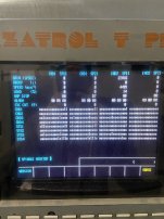
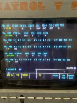
If someone can shed some light on this that would be appreciated. I can post the programs if necessary.
 
Are you doing any work on the sub? Or just using the sub to pull your bar? (bad joke there)
I have plenty of programs that use the sub to just do a bar pull and go home.
1 program can do it all. Never used 2 programs.
 
explain this: Then when it gets to the mill drill op it doesn't know if its engaged or not. The light on the controller is not lit up
pls.

the light?

take a picture of Diagnostic screen where BITS reporting status of Spindle controller can be seen. It is a bunch of 0000 and 1111 showing communication in between NC and MDS unit
 
Last edited:
explain this: Then when it gets to the mill drill op it doesn't know if its engaged or not. The light on the controller is not lit up
pls.

the light?

take a picture of Diagnostic screen where BITS reporting status of Spindle controller can be seen. It is a bunch of 0000 and 1111 showing communication in between NC and MDS unit
I’ll have a look up in my parameter book which bit show the status of the C axis of the main spindle.

The light/button I’m talking about is on the operator panel. It’s the button where you calibrate the main spindle on startup and disengage the spindle so it will spin freely. Or press it again to engage the C axis. That light is off all the time. But usually it’s working no problem.
 
I guess for T plus control with MDS-B-SP unit you can go into 1131 mode and see actual status of signals going from NC towards MDS and back. To see if it stays in servo mode and if it was commanded to leave it.
 

Attachments

  • IMG20230227095052.jpg
    IMG20230227095052.jpg
    550.8 KB · Views: 8
  • 22.jpg
    22.jpg
    127.7 KB · Views: 8
  • 2222.pdf
    710 KB · Views: 8
I guess for T plus control with MDS-B-SP unit you can go into 1131 mode and see actual status of signals going from NC towards MDS and back. To see if it stays in servo mode and if it was commanded to leave it.
How do you get into that screen ?
 
VERSION , most right button and type 1131, press INPUT , go back into VERSION/ DIAGNOSTIC and somewhere u will see SERVO and SPINDLE monitors.

You can see here INPUTS and OUTPUTS and also SPEED REACHED and RUN COMMAND. I guess if everything works perfect than SPINDLE CONTROL MODE SELECTION COMMAND signals should match in D/I and D/O.

If NC commands to go into C-axis, MDS should report that it is in this mode. If NC commands to run 1000RPM, MDS should report that it is spindle mode and RPMs are achieved.

That is just to try to understand why it stays in C-axis mode unless u press EMG or RESET
 
Last edited:
VERSION , most right button and type 1131, press INPUT , go back into VERSION/ DIAGNOSTIC and somewhere u will see SERVO and SPINDLE monitors.

You can see here INPUTS and OUTPUTS and also SPEED REACHED and RUN COMMAND. I guess if everything works perfect than SPINDLE CONTROL MODE SELECTION COMMAND signals should match in D/I and D/O.

If NC commands to go into C-axis, MDS should report that it is in this mode. If NC commands to run 1000RPM, MDS should report that it is spindle mode and RPMs are achieved.

That is just to try to understand why it stays in C-axis mode unless u press EMG or RESET
I’ll test tomorrow and report back results. Thanks so much!
 
when it stops again and u think something aint right here, Take few pictures:
-Spindle Diagnostic D/I and D/O
-PLC signals ( attached picture)

these are two most informative to understand what is happening here
 

Attachments

  • xvvxcv.jpg
    xvvxcv.jpg
    580.6 KB · Views: 4
Here are the screen shots of the spindle issue. The first spindle monitor image is before the issue. The second one is after. Note that when it stops the MDR spindle does turn on but no motion happens on X and Z. The PLC monitor page is current with the spindle in a locked position.
 

Attachments

  • DDC4C355-9135-4A75-A763-7DE1A5561A67.jpeg
    DDC4C355-9135-4A75-A763-7DE1A5561A67.jpeg
    1.8 MB · Views: 4
  • E0679C97-69EE-4406-A312-07592F89CE9C.jpeg
    E0679C97-69EE-4406-A312-07592F89CE9C.jpeg
    1.8 MB · Views: 4
  • 4E590A43-3C5B-499A-A5FF-6FB0E42C78EB.jpeg
    4E590A43-3C5B-499A-A5FF-6FB0E42C78EB.jpeg
    1.9 MB · Views: 4
  • F4E47A18-66AD-4975-AACD-720F5430436C.jpeg
    F4E47A18-66AD-4975-AACD-720F5430436C.jpeg
    1.9 MB · Views: 3
I think I figured it out. For some reason the way I made my bar pulled part of the program with the sub spindle is causing the main and sub to sync. And since im not running the sub it doesn’t want to continue past a certain point in the program. I put an M 512 to cancel it and the program runs now.

So I guess my next question. What is the best practice Mazatrol program to do a bar pull with the sub spindle. Here is how I programmed it now. Since this is the first time trying this it’s probably not correct.
 

Attachments

  • 2FA01A87-0BF8-40A4-9191-D20E87A38921.jpeg
    2FA01A87-0BF8-40A4-9191-D20E87A38921.jpeg
    1.7 MB · Views: 7
  • C31731CA-527C-4178-9D93-615CD17F4BB1.jpeg
    C31731CA-527C-4178-9D93-615CD17F4BB1.jpeg
    1.8 MB · Views: 7
it does looks like M512 is to cancel M511 which is a SYCHRONIZATION REQUEST.
Without M512 they both sit together in synchro mode , calibrating speeds or positions. U can probably go into PLC ladder and see what M511 does, to put your mind at easy.

I am not a machine operator. No idea how to deal with Mazatrol. I know how machine is built and that is all I need to know ;)
 
Last edited:


Back
Top