What's new
What's new

Making an angled strait edge

Gard

Aluminum
Joined
Mar 18, 2016
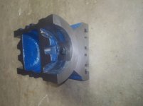
I started with a rough casting I bought from Denis Foster and will document my progress. I am a hobbyist machinist and beginner at scrapeing so any comments or suggestions will be appreciated. A search for "18" Iron Straight Edge Featherweight Raw" will show what I started with, I contacted Denis Foster directly, email][email protected][/email] He has documented how he machines the raw castings, [url] clearly has a well developed process for machining but I decided to machine it myself as I currently have more time than money. I was very impressed with the shipping, it arrived inside a fitted wood box. I first tried hand scrapeing the raw casting, this resulted in just some dust (as expected) so I gave up on that. Next I went at it with the 7" angle grinder, it took a couple of hours to get the bottom reasonably flat.
KIMG1026.jpg
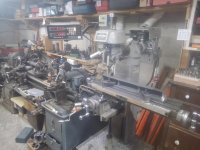
I did some scrapeing on the ground surface and found it took a bit of work to get thru the fairly deep grinding scratches. But now I have a surface that can be clamped to the milling table. In hindsight I could have just ground 2 flat areas under the clamps and ground everything else a little lower. My milling machine only has 15" of travel so milling will need to be done in steps. First the center area of the top and sides, machined very well with standard end mill.
KIMG1027 (1).jpg
Next the part was flipped and held in the vise to machine the bottom surface with a fly cutter. The part needed to be shifted in the vise to machine the entire bottom. Positive rake seemed to work better than negative that is often recommended for cast iron.
fly.jpg

more to come
 
In hindsight I should have done another iteration to get all surfaces closer.After a couple of hours of hand scrapeing I have the bottom reasonably flat, I suspect this may move some when I machine the sloped surface. You can still see the 2 round spots that were machined too deep when the pare was repositioned
scraped .jpg
I also scraped the back of the bottom as this will be a reference for milling the angled surface. I purchased a tilting table and 3" end mill from CME. First I remachined the entire top narrow surface using the end mill and vise in 2 steps. Next I mounted the vice to the tilting table, tramed everything and machined the angled surface in several steps. This small mill seemed most happy at 600 rpm with a depth of cut 0.005" Took of 0.045" total
KIMG1039.jpg

KIMG1045.jpg

I hope I have the correct images here
 
I think the bottom is flat within a couple of thou. Next up I need to build some kind of sled to hold the casting as I scrape this angled surface.
 
When I made them I would order a square piece of gray iron G2 from Dura-Bar and have them cut it corner to corner as they have saw that can do that. It was cheap as heck. These guys sell it too. Speedy Metals - Cast Iron or Dura bar Stock Sizes I would check them and Dennis and see who is cheaper. One good thing about extruded gray iron is there is no porosity and little if any stress.
 
My Scottish grandmom taught me the value of a penny, but she also taught me the value of good tools. In her case, looms and knives. A knife had to be balanced in the hand, have a sharp edge and good enough steel to keep the edge for a reasonable time. For that, good money could be paid. Her looms? Well she had three at one point, all well used but modified to have easy travel of the shuttlecock, and beautifully balanced foot action.

Why am I telling this family anecdote? Because Denis’s 18” casting feels good in the hand and allows me to feel hinging and get a good print. Worth every penny imho. Fact is, it can also function as a level and parallel. I use mine regularly, and thank him for his thoughtful design and good casting.

L7
 
When I made them I would order a square piece of gray iron G2 from Dura-Bar and have them cut it corner to corner as they have saw that can do that. It was cheap as heck. These guys sell it too. Speedy Metals - Cast Iron or Dura bar Stock Sizes I would check them and Dennis and see who is cheaper. One good thing about extruded gray iron is there is no porosity and little if any stress.

For those interested 2.25 square by 18” of grey iron from Speedy is 186 dollars shipped.

B34A9D70-3650-402D-8449-0862E530B655.jpg

I guarantee my straight edges to be cast by me from premium stock and to be free of any voids (never has anyone reported a void or hard spot) properly THERMALLY stress-relieved, boxed in a fitted custom wood case and shipped USPS priority within the US and internationally.

I am selling my 18 to PM members for 210 - 10% 189 plus 22 dollars (cost in the US and about 50 internationally) shipping. ;-)

By all means, decide what is your best deal.

But, far more importantly and actually germane to this post, reach out and offer friendly constructive advice to the OP who is clearly committed to ending up with a properly scraped straight edge that he can use for rebuilding his machines. I am pretty sure he is not posting here for price comparisons or cast iron shopping advice. (If anyone wants to start a thread on the relative merits of available straight edges and their pricing vs bar stock, I am well prepared to engage.). But that is completely off-topic here and will inhibit constructive and helpful dicussion for the OP. That is what this forum is about, right?

Denis
 
Relax Dennis, I have seen your SE's and they are good quality. I not knocking them, I was just telling the members the way I did it. It is an open forum for those with value can help others.
 
When I made them I would order a square piece of gray iron G2 from Dura-Bar and have them cut it corner to corner as they have saw that can do that. It was cheap as heck. These guys sell it too. Speedy Metals - Cast Iron or Dura bar Stock Sizes I would check them and Dennis and see who is cheaper. One good thing about extruded gray iron is there is no porosity and little if any stress.

I am curious about what size stock you would of used for a 18" angles strait edge?

I considered making one from a welded and annealed section, I am glad I did not go that way. I messed around with a few chunks of steel and concluded I would want a section at least 1.5 in square plus the angled part off one side. I also looked at the durabar but could not picture my small mill removing enough metal to make a round or square shape into a triangle or trapezoid shape, I did not consider they could cut it lengthwise.

I am very happy with featherweight raw casting, It has been easier to scrape than the few other things I have tried and I really like the design. I think if I was to machine another one, even on a small mill like mine, I would consider the rotisserie concept like Denis used. I would need to modify the end blocks so they clamped to the table under the SE so the SE could be located very close to the end of the table, then could be shifted to the other end of the table to machine the rest of the surface. If all milling was done with a flycutter or face mill there would be no need to align the rotisserie to the mill X axis.
The way I machined it forced me to buy a angle table so that is good. The table only cost about $100 and seems to be well built with one exception, I need to make new "washers" that go under the clamping bolts.

I also need to come with a better way to tram the mill, the horizontal shaft that holds the head and motor is clamped with 2 bolts. I have been adjusting the tram by tapping the head with a plastic hammer, get zero zero on the dial indicator, then it moves out 5 or 10 tho when I tighten the bolts. I think I am going to make a handle about 3 feet long I can clamp to the shaft to rotate it while the bolts are almost too tight then snug them down the last bit. Is there some simple secrete to this I am missing? I understand larger more expensive mils have some kind of fine adjustment feature.

I got some serious chatter with the face mill at higher feed or depth of cut, not sure to what extent it is the $100 face mill, inserts, spindle or the vice on top of the angle block on top of the table but it worked better at faster speeds with smaller cuts. This was my first experience with insert cutter on the mill, the inserts look dull compared to an a HSS end mill or fly cutter.

I wish I could help with the tram issue of your Clausing mill. It looks like the head is supported by a round shaft gripped by a split collar. I think your idea of snugging it partially and then levering it into tram may be a good idea. That said, perfect tram as indicated by a DI in the spindle and trailed across the table may not result in perfect FUNCTIONAL tram. Bearings in the spindle and possibly some flexion of the head support will likely cause the cutter to nose in a bit as you traverse the cut. So, I usually try to indicate pretty good tram and make roughing cuts. But when I get down to final cuts, I adjust the tram so that I see fine lines made by both the leading and trailing sweep of the face mill I use. This has to be done by trial and error and only works in one direction as flexion and bearing slop will result in a different orientation of the face mill when traversing left vs right. This sounds sort of difficult, but in practice it is not and I think is charecteristic of most mills whether they weight 500 or 5000 pounds. For the heavier and more rigid machine bearing distortion amy be most of the problem and not so much flexion but still can be a factor.

I do think the rotisserie method is a good one. The more rigidity one can establish without introducing casting flexion, the better. I have used wood wedges and/or weights on the casting to good effect if I encounter chatter. I get my casting machined to within a thou to 1.5 thou of flat. But, that is perhaps not really necessary when doing work for yourself. It does not take that long to scrape off a high end or center that may be out a few thou. More work than a nice flat machined surface? Yes. But necessary? Maybe not.

I doubt the face mill itself is the source of chatter. I use one with inserts intended for cast iron. Those inserts are not the shiny sharp ones designed for aluminum. But still, my 1 HP Bridgeport makes nice shavings with fairly deep----.030" deep cuts with the head rotating at maybe 200 RPM or 175 SFPM. When I am using a 15 ton Lucas Horizontal to mill a 36 camelback or 26 prism depth of cut is limited by how well I can hold the casting as I suspect it would make .500 deep cuts without even particularly noticing. But holding the casting without undue force/distortion is impossible. SO even there I have to limit myself to .050 deep cuts or risk shifting the casting due to cutter pressure. Either way, I love the sound of nice soft grey iron being cut by a good cutter. There is a distinct hiss as the cutter just walks down the casting. And there is very little heat generated unless the inserts have reached their lifetime limit. The ways on that old Lucas are so good that the 26's and 36's are flat to better than a thou unless I have inadvertently torqued the casting. Once in a great while I have to take one back out to the shop and remount it and make a final cut to get the desired flatness. That serves as a good jerk on the reins to remind me to be very mindful of avoiding torquing the casting, but still getting everything solid enough to make the cut. It can be a bit of a dance. And always requires carefully focused attention.

Anyway, It is interesting to see your progress. I hope someone more familiar with your particular mill can provide some better insight into how to get the best possible performance. I am confident you are going to work away at the problem until you get it solved.

Denis
Added: I read your post while I was out at my foundry today casting a couple of 18's. I pulled them out of the sand late this afternoon and was happy to see they look great. Every time I dig castings out I hold my breath. There are lots of ways for a casting to end up being sent to the remelt barrel and just one way for them to come out right.
 
Last edited:
I wish I could help with the tram issue of your Clausing mill. It looks like the head is supported by a round shaft gripped by a split collar. I think your idea of snugging it partially and then levering it into tram may be a good idea. That said, perfect tram as indicated by a DI in the spindle and trailed across the table may not result in perfect FUNCTIONAL tram. Bearings in the spindle and possibly some flexion of the head support will likely cause the cutter to nose in a bit as you traverse the cut. So, I usually try to indicate pretty good tram and make roughing cuts. But when I get down to final cuts, I adjust the tram so that I see fine lines made by both the leading and trailing sweep of the face mill I use. This has to be done by trial and error and only works in one direction as flexion and bearing slop will result in a different orientation of the face mill when traversing left vs right. This sounds sort of difficult, but in practice it is not and I think is characteristic of most mills whether they weight 500 or 5000 pounds. For the heavier and more rigid machine bearing distortion may be most of the problem and not so much flexion but still can be a factor.

I doubt the face mill itself is the source of chatter. I use one with inserts intended for cast iron. Those inserts are not the shiny sharp ones designed for aluminum. But still, my 1 HP Bridgeport makes nice shavings with fairly deep----.030" deep cuts with the head rotating at maybe 200 RPM or 175 SFPM.

I believe you are correct about the chatter, I made new clamping washers for the tilting table. An old cast iron piston was machined to the correct outside diameter, sections cut off and the inside milled flat with the 3 inch face mill. It machined nice at 600 RPM but chips were ouchy. At 350 RPM it also works very nice with cooler chips. No sign of chatter so I think my issue was with fixturing not the mill. The crude stamped steel washers was the weak point of the table. With the new ones it rotates very smoothly and the wrench fits better. Now I can put the table away and know it will be ready to use next time I need it.

KIMG1048.jpg
KIMG1049.jpg
KIMG1051.jpg


Thanks for the comments on traming, I have convinced myself I need a fine adjustment feature so I can move it a repeatable distance (not so easy with the plastic hammer). I have gone thru several designs in my head and think I have something workable so now the welding and cutting part. Congratulations on the casting that sounds like a fun process.
 
Gard,

Yes! Those washers you made look soooo much better suited to the task than what was supplied with the table. The cheap import tools often are made with 95% good parts, but are then rendered nearly useless by some feature or component that is poorly executed. Finding and fixing those shortcomings can make a world of difference. My bet, based on having numerous ground import tools, is that the basic grinding on the table and base are spot-on, but the slots, fixing bolts, etc are sketchy at best. I suspect you just significantly improved your setup.

Your efforts to design and fabricate some sort of screw-driven fine adjust sounds like a very good idea.

To reduce chatter in your angled setup further, if you can weld up a couple fixtures to be clamped or bolted to the ends of the casting and the to the table without inducing torque (I like bolts with spheroidal washers) I think you will help yourself. Also, experiment with holding a dead-blow hammer against the casting while milling. Just touching it with a stick can dampen harmonics, sometimes dramatically, but a heavy hammer, especially a shot-filled dead blow, can really help. Also, I avoid clamping the flat surface of the prism to “ flat” table even after stoning off all the micro bumps on the table. I stone it and then “two-point” it on feeler gage stock to reduce twist and bending when milling the top rail. Again, for personal work, a little distortion can quickly be scraped out, but might as well make it as easy as reasonably possible for yourself.

Denis
 
Strongly agree with the comment from Denis that reducing twist and bending when setting up a part for machining makes life easier later. I cringe when watching some youtubers set up their castings for machining by cranking uneven surfaces down to table, then have to waste time surface grinding and have many more cycles of scraping as well. The grumpy old English toolmakers who gave me lessons were right- do it properly from the beginning.

L7
 
By the way, one of the things that helps me adjust tram is to place a dial indicator on a magnetic base on the table with the finger against the face mill. Then I go ahead and tilt the head a little bit left or right to adjust tram and watch the dial indicator movement. That helps me avoid the two far left now too far right now too far left problem. It takes a surprising amount of rotation of the head to adjust for a small amount in degrees of change in the face mill attitude. In other words I expected I would only change the position of the face mill a thou or so to make a noticeable tram change. But, in fact, I often move that face mill three or four or even 5 thou to make a small change in tram.

Now headed to the foundry to pack a second mold and melt some iron to fill two. Then I’ve got an 18 to mill for shipment tomorrow. Christmas holidays seem to be busy as I think a lot of folks tend to gift themselves castings they’ve be thinking about for a while. ;-)

Denis
 
The way I hold a Prism or angled SE is to drill and tap holes in the end, Depending on the size. Minimum of 3/8 and then I use jam nuts on the bolts. Then set 2 mill vises on the mill table, set the SE on V-Blocks and clamp down on the jam nuts on the bolts. You can loosen the nuts to adjust the angle. Simple as heck. I also used to grind the SE's on my surface grinder using magnetic V blocks. Gard if we ever do another class up in Springfield VT at the Gear Works, come on over an say hello, or take the class. Rich
 
The way I hold a Prism or angled SE is to drill and tap holes in the end, Depending on the size. Minimum of 3/8 and then I use jam nuts on the bolts. Then set 2 mill vises on the mill table, set the SE on V-Blocks and clamp down on the jam nuts on the bolts. You can loosen the nuts to adjust the angle. Simple as heck. I also used to grind the SE's on my surface grinder using magnetic V blocks. Gard if we ever do another class up in Springfield VT at the Gear Works, come on over an say hello, or take the class. Rich

Nice, I like the idea of the bolts in the ends along with the V block, seems like this would make inspection easer by using those same V blocks on the surface plate with an indicator. My mill is too small to have a vise at each end but I think I could weld up something along the line of what Denis uses but rotated so the hold down bolts to the table are under the SE.
Thanks for the offer, I would like to stop by if there is another class in Springfield, not sure a full class could fit in my budget but it would be a good excuse to stop by the American precision Museum again.

I am hopeful all the machining is good enough now and I can proceed with scraping the angled and top surfaces, just seems like there is always some other project...
 
The way I hold a Prism or angled SE is to drill and tap holes in the end, Depending on the size. Minimum of 3/8 and then I use jam nuts on the bolts. Then set 2 mill vises on the mill table, set the SE on V-Blocks and clamp down on the jam nuts on the bolts. You can loosen the nuts to adjust the angle. Simple as heck. I also used to grind the SE's on my surface grinder using magnetic V blocks. Gard if we ever do another class up in Springfield VT at the Gear Works, come on over an say hello, or take the class. Rich

One caution to a machinist electing to use the paired vises: A pair of mill vises with smooth (not vee-grooved) jaws should allow the SE to be clamped without induced strain if the user first clamps the drilled and tappped studs in the unfixed vises. That way the vices can move around a bit to allow for imperfect alignment of the bolts. Once they have found their relaxed alignment, then bolting or clamping down the vices can be done. If the smooth-jawed vises are first clamped to the table at a convenient spacing and then the SE drilled and tapped bolts are clamped by the vises, any malalignment of the bolts will cause the bolts to flex and will induce strain (warping) into the SE and your nicely straight flat surfaces will relax into a warped condition when removed from the vise. And similarly, if vee-grooved vise jaws are used, unless the two bolts are perfectly parallel to the vee-grove axis and are exactly collinear, strain will be induced.as the bolts try to align with the vee grooves. Exactly how precisely collinear bolt holes could be drilled into the casting in the first case is unclear to me. So, best assume they are not ideally aligned and allow them to find their relaxed orientations if you are looking to do as ideal a job as practical.

That is why I put my 18's and 26's on a "rotisserie" By using spherical washers at the locations indicated in the image below, I can allow the reinforced angle iron supports to float in all axes while I tighten down the bolt used to hold the SE. Then I tighten down the hold-down bolts in the angle brackets and relax the bolts in the SE a bit just in case the brackets rock a little as they are clamped down. Then I snug up the bolts again and block it in to prevent rotation as shown.

Spherical washer locations.jpg

Spherical Washers.jpg

This makes a good solid setup with which I can get very flat surfaces. None of this is difficult, but there can be pitfalls that are not so obvious.

I can see where Gard's idea of turning the angle suppport brackets each 180 degrees would compensate for table length limitations.

Denis
 
Last edited:
That is why I put my 18's and 26's on a "rotisserie" By using spherical washers at the locations indicated in the image below, I can allow the reinforced angle iron supports to float in all axes while I tighten down the bolt used to hold the SE. Then I tighten down the hold-down bolts in the angle brackets and relax the bolts in the SE a bit just in case the brackets rock a little as they are clamped down. Then I snug up the bolts again and block it in to prevent rotation as shown.Denis

Not sure if there is room but would it be a good idea to put a spherical washer set under the bolt head on the inside of the SE?
Thanks,
David
 
Not sure if there is room but would it be a good idea to put a spherical washer set under the bolt head on the inside of the SE?
Thanks,
David

I do not think there is room for a washer set inside the SE, at least, not near the center of the end piece. I think centering that hole more or less is desirable for good work holding. I suppose one could turn down the diameter of pairs of spherical washers.

More importantly, I don’t think there would be much to gain from washer sets under the bolt heads. The bolt heads seat on the end pieces very close to the center of the hole and thus produce only a relatively small amount of off-axis pull. I have not had that degree of eccentricity cause any noticeable distortion. If one wanted to minimize that eccentricity more, just turning down the bolt head until it was just slightly larger than the hole would help. And doming the under-surface of the bolt head would help. I don’t worry about the bolt head or it’s seating though.


What I do think is important is to avoid jamming the faced-off end of the casting against the fixture bracket. As made, the brackets are simple weldments made using common heavy angle iron. So, their faces are approximately at a right angle to the base. (Incidentally, I do relieve the mid portion of those bracket bases to help them sit more firmly on the mill table.). But, I am sure they vary some from a right angle. And the faced-off end of the casting is pretty flat, but it is not precisely parallel to the other end face and it is not precisely at right angles to anything. It does not need to be. Finally, even if the end brackets were ground and scraped to near perfection and the end faces were also, I would still use spherical washers as, at least in my shop, nothing is perfect and the washers eliminate binding and torquing from mating non-parallel surfaces.

I am looking forward to seeing how your casting blues up and to seeing the progress you will make scraping it in.


Denis


Another reason for spherical washers in Denis’s setup is typical table sag. The Bport tables I’ve measured are anything from 2thou sag to over 30thou in a 42” table!

L7
 
How to tram a mill-drill.
I found it much easier to tram the mill if I have the clamp bolts as tight as possible when adjusting the head, this reduces movement when it is clamped tight. I moved the head with a long wood stick, prying against the extended quill or motor mount and the mill column. Decided to make a fine adjustment attachment for the mill. Started with 1.125 shaft (actually annealed torsion spring from old Astro van) and 2 ea 0.25 thick plates. Welded then bored 2.995 hole. This took awhile, probably would of been quicker to grind a treepanning bit?
KIMG1052.JPG
Next welded on the other bits, fit a couple of 10-32 adjusting screws and sawed it in 1/2. Probably should paint it but can't wait to try it out.
KIMG1054.JPG
A little adjustment and fits perfectly
KIMG1064.JPG

The opposing adjustment screws made it very easy to adjust tram. For years I have gone to every extent to avoid changing the head because it was such as a pain to get it trammed back in. I wish I had made something like this years ago. With this mill I can move the head closer and further from the column as well as rotate tram and rotate about the column so that will help being able to locate the head over a variety of parts.
Another view of mill, I chucked up a drill rod and adjusted the clamping bolts to the point where I could just barely tilt it by hand then marked the bolts
KIMG1055.JPG


Back
Top