What's new
What's new

Making an angled strait edge

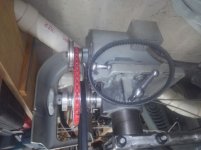
Decided to make a fine adjustment attachment for the mill.
Gard, so, using a little ingenuity, you overcame a significant limitation of your machine's design and now have a machine you can use much more easily and will not hesitate to change tram when needed. Those adjusters will come in handy when you tweak for functional tram, I can assure you.

Denis
 
Gard, a few posts back you mentioned cutting rates and depth of cut on a face of the 18. Today I was milling a couple 18's since I was snowed in with 10+ inches of snow and 8 deg F temps---quite unusual here.

I took note of the settings on the little Bridgeport 1 HP mill I use to cut these faces and the top rail.

I was cutting a 40 thou DOC using a 4" face mill using APKT 1604 inserts. RPMs were about 300 and I run the feed on the table as fast as I can keeping an eye on the amperage my VFD is putting out as it is set to allow a little over 4 amps on the 240v 1 HP motor (that is running it at a little over its rated 1HP). I am able to run the table at about 6 to 7 IPM at 4 amps. When I've milled off about .125," I reduce the DOC to around 4 thou and increase the RPM to 375 (the max in back gear on my machine) and reduce my travel to 2 IPM. That seems to produce a very good finish with enough tooth for good scraping and also very flat. I claim .0015 flatness, but I think I almost always get the faces flatter so that they are often much closer to .0005"

Here is a 30 sec video of the rough cut as it is in progress:

Milling 18” at 6IPM and .040 DOC and 4 amps - YouTube

I thought it might be of interest to have some actual cut setup figures and see what is involved. It is noteworthy that there is zero chatter with those cut parameters.

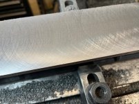
Here is an image of the cross-hatch pattern produced for the final cut.finish cut.jpg

FWIW,
Denis
 
I thought it might be of interest to have some actual cut setup figures and see what is involved. It is noteworthy that there is zero chatter with those cut parameters.

Here is an image of the cross-hatch pattern produced for the final cut.View attachment 337965

FWIW,
Denis

Denis, you are getting a very nice surface finish and flatness. My face cutter also came with those inserts, they tell me APMT1604 is the same as APKT1604 I was able to get a reasonable DOC when I had rigid enough clamping.
I always thought I was limited by HP on my smaller mill (3/4 hp) but when using the fly cutter I realized the problem was the belts were slipping. There was improvement when I used a prybar to tension the belts. I bought some new cogged belts but then realized the problem was the smallest diameter pulleys groves were worn to wide, anyone have any suggestion for a source of new pulleys or will I end up making new ones or perhaps modifying these?
With the new cog belt installed and tensioned I could still make the belt slip by hand. Next I tried "power twist v belt" a link type belt which is just a little wider, and seems to fit much tighter, I cannot make it slip by hand. I look forward To trying it out with some heavy cuts.
I saw the same thing with my table saw, the pulley diameter is significantly smaller than what the belt companies recommend.
KIMG1076.JPG
KIMG1077.JPG
 
Denis, you are getting a very nice surface finish and flatness. My face cutter also came with those inserts, they tell me APMT1604 is the same as APKT1604 I was able to get a reasonable DOC when I had rigid enough clamping.

APKT and APMT inserts have the same geometry. The K vs M indicates the tightness of tolerance on the insert itself. For general work, the lower toleance inserts should be fine. However, there are tons of variations on APKT inserts with the inserts having chip breakers, radii, cutting angles etc all optimized for various materials. I am using an Ingersoll insert optimized for cast iron. It seems to hold up very well to CI when other inserts with smaller radii and sharper corners break down.

I always thought I was limited by HP on my smaller mill (3/4 hp) but when using the fly cutter I realized the problem was the belts were slipping.

The main reason I posted my cut parameters and finish result was not to say my setup is an optimal production setup. Far from it! But, I have learned to get better performance out of the diminutive BP than I initially thought possible with those improvements mainly being my own learning. A more convenient and rigid fixturing system, better inserts, a couple of reasonable (import) facemills, finding the optimal RPMs and table feed all worked together to make things work better. Most of that learning was by persistent trial and plenty of error. I also noted in an old post by Stephen Thomas his endorsement of APKT facemills as working well for him. That led me to pursue that avenue.

There was improvement when I used a prybar to tension the belts. I bought some new cogged belts but then realized the problem was the smallest diameter pulleys groves were worn to wide, anyone have any suggestion for a source of new pulleys or will I end up making new ones or perhaps modifying these?

Finding new pulleys should not be too challenging. Pulley geometry is not fixed over various pulley diameters as you may know. If you were to make new pulleys, you should read up on pulley wall angles vs belt size vs diameter. I would be much more inclined to just order pulleys from a source that provided good documentation of their pulleys that will fit a known application---I am thinking McM as opposed to ordering from eBay or Amazon. You might be able to increase your pulley sizes if you did a little figuring and changed the mating step pulley sizes. Pulleys are relatively cheap and, yes, having good ones is essential to machine performance. Maybe consider a 3-phase motor and VFD as that allows much more fine tuning of RPM. Orrrr, maybe consider a larger and more robust mill?

With the new cog belt installed and tensioned I could still make the belt slip by hand. Next I tried "power twist v belt" a link type belt which is just a little wider, and seems to fit much tighter, I cannot make it slip by hand. I look forward To trying it out with some heavy cuts.
I saw the same thing with my table saw, the pulley diameter is significantly smaller than what the belt companies recommend.
View attachment 338145
View attachment 338146
Responses bolded above.
Denis
 
Thanks for all the comments. It was nice to see your cutting parameters were roughly in line with mine. I must admit I have never done the calculations or tables on HP vs cutting depth vs RPM vs feed. I tend to set RPM with a rough guideline, then go by ear on the others and crank the handle based on desired surface finish and HP.

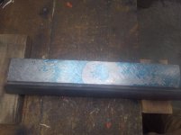
I have gotten back to the straight edge. I made a cradle to hold it on the work bench. I will attach some photos of the progress, I decided to keep track of what was happening so I counted the number of cycles, time and measured the total metal removed which worked out to about 1 mil average across the angled surface total. I used Prussian blue then switched to white titanium mixed with mineral spirts. Hand scraping with about 3" radius carbide. About 5 hrs working on it so far, I am thinking it is close to "good enough for who its for" as my father in law used to say. I am a beginner at this scraping thing so any comments or suggestions are appreciated. Is this a reasonable amount of time for where I am at?
KIMG1079.jpg
KIMG1084.jpg
KIMG1084.jpg
KIMG1086.JPG
KIMG1096.JPG
KIMG1109.JPG
 
Cut out a 1 inch square of paper, some areas are better than others, it seems to me the whole PPI thing is somewhat subjective depending on how much of what kind of medium is used.
I was a little surprised that with the prussian blue it tended to hinge a little too close to the ends but with the titanium (red led substitute) it tended to hinge closer to the middle. I tried on 2 different sides of the granite surface plate with slightly different results so I know my surface plate is not perfect.
Other than the obvious of buying a Biax or taking a class, anything else I should be doing different?
KIMG1110.JPG
 

I think you are applying the blue too thick. When you get to finishing your blue should be wispy thin. Your high spots seem to wash together too much. Also, the outlines of the high spots do not appear clearly delineated. That would indicate that you're not rubbing the part hard and long enough. One way I got the ink right on the surface plate is by spreading it thin in one corner and then using a clean brayer to transfer it to another area. if you use pink granite the blue should just look like a light stain, on a black stone it should look like a light mist. Use a contrasting color on the cast, it makes the print more pronounced.
 
Gard,

You have come a long ways from your raw casting, machining managed on a small mill with minimal fixturing tooling, and then initial scraping results which have steadily improved. And you are getting some good advice. That coupled with your evident work ethic, determination, and willingness to seek and accept advice is certain to result in a great straight edge. I am following your progress with interest as I am sure are others. Keep on scrapin!

Denis
 
I think you are applying the blue too thick. When you get to finishing your blue should be wispy thin. Your high spots seem to wash together too much. Also, the outlines of the high spots do not appear clearly delineated. That would indicate that you're not rubbing the part hard and long enough. One way I got the ink right on the surface plate is by spreading it thin in one corner and then using a clean brayer to transfer it to another area. if you use pink granite the blue should just look like a light stain, on a black stone it should look like a light mist. Use a contrasting color on the cast, it makes the print more pronounced.

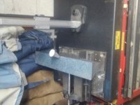
Thanks for that, I did try to reduce the amount of blue as the scraping progressed. With the thick blue I was scraping large areas, as I got closer to seeing blue everywhere, I used less blue on the stone but found it hard to see and much harder still to photograph. I generally add a little more blue to the stone with the brayer for each cycle, completely cleaning each them only if I saw particles of crap.

I tried a couple of cycles with the white on the part and blue on the stone, this did not seem to help much to my eyes. I will give it another try with less blue on the stone. Do you end up cleaning the stone between with each cycle?

The white on the part seems to show up the high spots but I wonder if I moved from blue to white too soon. I think I have some other colors, yellow and red, perhaps I will give them a try.
 
I think you are applying the blue too thick. When you get to finishing your blue should be wispy thin. Your high spots seem to wash together too much. Also, the outlines of the high spots do not appear clearly delineated. That would indicate that you're not rubbing the part hard and long enough. One way I got the ink right on the surface plate is by spreading it thin in one corner and then using a clean brayer to transfer it to another area. if you use pink granite the blue should just look like a light stain, on a black stone it should look like a light mist. Use a contrasting color on the cast, it makes the print more pronounced.
Thanks for the pointer on applying blue to a corner of the stone and then transferring to the work area. I think I had seen that suggested somewhere else and it really does seem to work better and faster. I marked up the angled surface again with the titanium on the SE and lighter blue on the stone and got a similar pattern to post #26. I think I will probably do a few more cycle on this side.
KIMG1112.jpg

Next I flipped the SE over and checked the bottom. I was very happy to see it was about the same as it was before I machined the angled surface. I was afraid that the machining might of caused some movement due either to machining forces or stress relief. So I think this is Proof Dennis did an excellent job of stress relieving the part and I did not screw it up with my machining. I did a couple more cycles on the bottom using just the blueing. As I am using less ink There are a couple of areas (less than an inch or so) that are not making good contact but it is getting better each cycle. It seems almost addicting to me, just one more cycle tonight... At my progress level its hard to imagine someone could make a living doing this
 
This is the bottom after a couple of more cycles. I fixtured it up on an adjustable tilting table and checked it with a 0.1 mil indicator, found the end low by a couple of tenths, I marked those areas and went lighter there for the next couple of cycles.KIMG1122.JPG

Here is where I ended up, I think I am done now. The high spots are all within +/- 0.1 mils so about at the limit if my current tools.
KIMG1124.JPG
KIMG1125.JPG


Back
Top