What's new
What's new

Mazak Nexus - Chuck Sensors make no Sense.

Isak Andersson

Aluminum
Joined
Nov 3, 2021
Hi guys. Sorry for the little pun there in the title but this is something that has been bothering me since we first got our first Mazak machine. How are the chuck sensors actually supposed to work? It seems no matter how I place the sensors I'm either getting some kind of error or I'm getting reduced travel of the chuck which isn't good either. I mean, even the Mazak tech guy couldn't get the sensors right.

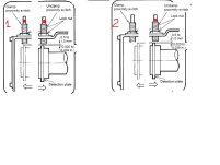
So from what I understand both sensors should be on when the chuck is clamped right? One is on and the other is off when the chuck is open and vice versa in the end position, correct? But how do I know which one is the "open" sensor and which one is the "closed" sensor?

These are the errors I'm getting:
One sensor is off in the end position: 215 Chuck System Malfunction
Both sensors are off in any position: 224 Chuck Sensor Malfunction

Error 224 makes sense to me as both sensors should never be off at the same time but what's up with error 215? Why is it considered an error for the chuck to reach its endpoint? Is there a parameter maybe that can change this behavior? The reason I'm asking is that I need a way to monitor the chuck position in a macro program, but if the machine alarms out I can't do this, obviously. There has to be a way right?

BTW. When I say off I mean that the lights are off on the sensors. Maybe this is actually considered to be on, though, by the controller. I wouldn't know which.
 
Last edited:
I will draw you a picture how they are meant to be operated.

1. there are CHK_EXTERNAL and CHK_INTERNAL
2. Normal 3 jaws chuck and collet chuck
3. two proxy switches, clamp/unclamp
4. two pressure switches (option, parameter activated)
5. Timer inside PLC to make a decision that material is chucked (parameter activated)

this attached picture is just one scenario for 3 jaws chuck proxy based chucking.

Picture 2: UNCHUCK is on the right and is always ON when chuck is OPEN ( I think this is mandatory for PLC to know that CHUCK is fully open).
When material is clamped, both proxies are OFF, as the detection plate is somewhere in between them. Machine can use TIMER or PRESSURE switch to detect end of the movement ( I think PLC needs some way of confirmation in this case, either pressure or timer based or just not reaching leftmost proxy, means there is a material and it was clamped)

Picture 1: Unclamp - RIGHT proxy is ON. CLAMP- Left proxy is ON. Machine knows that there is no material inside the chuck as it jaws travelled till their mechanical limit or during chucking the material was pushed out of he chuck. That is supposed to be misschucking or NO-WORK signal for PLC)

A lot of people just have one proxy adjusted as UNCLUMP and clamping is based upon TIMER or PRESSURE switch confirmation. Normally your electrical diagram would have heaps of CHUCK related parameters to select the way it should work.

P.S. that is how I understand it but then... inside PLC ladder the whole process is broken down into few lines of logic. What funny is that not a single MAZAK maintenance book explain how it works, like MAZAK deliberately trying to avoid proper explanation ;)
 

Attachments

  • Untitled.jpg
    Untitled.jpg
    140.5 KB · Views: 37
Last edited:
Chuck sensors are a pain in the ass. They are disabled on all my machines.
+1 I made an effort to use them on my brand new Integrex for a week. If you can't find it in the book, call mazak for the parameter. Not worth the time wasted.
 
dont give up. Dont disable them. I can break down PLC logic for your particular machine and we see all steps in chucking and unchucking =)
 
It's a parameter setting. I do not know what it would be on your control. It should be listed in the manual somewhere.
I've looked for it. Couldn't find it. Do you know what the name or description of the parameter is? Maybe what group its part of? Anything would help.
 
Dont disable them =) You cant get anything better than MAZAKy PLC logic. They were working on it for years. If it doesnt make any sense or doesnt work correctly, they are not mechanically adjusted
 
If it doesnt make any sense or doesnt work correctly, they are not mechanically adjusted
I think they are adjusted correctly now. The thing is sometimes I need to be able to run the machine even when the chuck is clamping on nothing. The way it works now it immediately goes to error 215 Chuck System Malfunction.

This is a problem if I'm doing bar-pulling work for instance. When doing synchronous rotation during the parting-off operation, the last part on every bar will only clamp on the sub-chuck so the main chuck will cause the alarm. The way I dealt with this in the past was to move one of the sensors so it never triggers but if I'm gonna do this I might as well shut them off completely.
 
have you considered changing the structure of you program?

Ex. have an EIA subprogram keep track of the length with a counter and for that last run simply change the program to not do the synchronous rotation? for the last part you would just do a simple transfer as if it were a chucker part.

you can run mazatrol sub programs from an EIA main program, and with just a bit of logic in it I think this would fix your issue.
 
Ex. have an EIA subprogram keep track of the length with a counter and for that last run simply change the program to not do the synchronous rotation? for the last part you would just do a simple transfer as if it were a chucker part.
Yeah, that could work. However, I would be a bit nervous if the bars are of varying lengths and the operator forgets to update the length variable. That could end badly, which is why I think it would be better to have a way to monitor the proximity switches directly and do the appropriate action based on that instead. If there only was a way to deal with that pesky error 215...
 
I think I need to look this sensor stuff up. I have 2 sub spindle Fusion lathes and a Smooth G lathe. One of the Fusion lathes always needs the Main clamped on something. The result is 1 good part worth of stub as drop. .625 dia x 2.5" long. What is going to suck is running the 5 gallon bucket of drops one at a time as Chuck Work, price of brass. I used to scrap them with the swarf but not now. Myself or an operator stuck at the machine for either a 55 second cycle or 100 second cycle.
 
2 solutions found for my situation. On my machine the left sensor (looking from back of spindle) alarms out if the chuck closes on nothing, light goes out. But both sensor lights stay on when running bars. So I loosened the screws and pulled the sensor full back and light now always on. Makes the difference between 36 and 37 parts/bar.
But also R49 parameter can be set to either SWITCH or TIMER. 0 or 1.
You must select HEAD ONE on the control panel for R parameters to show up on PARAMETER screen. That was why I could not find it at first. But looking for it while machine is running and it will pop onto the screen if working on HEAD 1. And it goes away when the sub takes over.


Back
Top