What's new
What's new

Measuring Taper with Gage Balls

Whatley

Cast Iron
Joined
May 23, 2013
Location
Texas
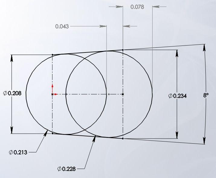
Hello everyone, I have some parts I am working on right now that have a 8° Internal/Female taper on a hole (Top of hole is: .234) and (bottom of hole is: .208)

I was looking through the site trying to figure out a way to check this dimension at the machine since our CMM guys take about a million years to check anything.

Several people mentioned Gage Balls, one larger and one smaller and doing some brain-smart math to figure the angle. I understand the concept and how it could work but Can anyone walk me through the process a bit in more detail? Or have a diagram with the relevant equation?


Thanks, Whatley.
 
Measure the distance between the centers of two balls of known size, then use the radius of each to calc the angle.

It'd be best if I were to draw this out, but I'm not able to now. CAD would also be very handy.
 
R = radius of large ball minus the radius of the small ball
L = distance from the top of the large ball to the top of the small ball

Included angle = 2*asin[R/(L-R)]
 
Maybe just me but I'm not getting how that helps.

Gordon

To use the spreadsheet:

Enter the mouth diameter in cell D33
Enter the hole diameter in cell D34
Enter the desired included angle in cell D32
Strike Enter key.
Cells D28 and D29 will then calculate min. and max size balls.
Now you get to select which available balls you have and enter the sizes in cells D30 and D31
Strike the enter key and H and HH will be calculated. That would be cells D35 and D36

Gene
 
I like the drawing in the spreadsheet - makes it clearer. I think Gordon was making the point that if the guy wanted to find the included angle using measurements (the OP's goal), the sheet did not give this number directly.

I would suggest that the formula above is not strictly correct. Suppose two balls, radii of r and R (small and large, respectively)
We put the small ball into our taper (making sure we have a way to get that ball out!) and using a depth gage measure the distance from a reference surface to the ball as l (small L).
Put the big ball in and measure depth L.
The difference between the small ball surface, adn the large ball surface, let's call "m", for measured difference. m = l-L
But this is not the difference between ball centers. That would be m - R + r. Call it d, for distance: d = m -R + r
But this is not the distance between the tangent point of the balls, nor is the taper diameter at the tangent points of the balls equal to r or R!
Draw a picture, and you realize that the distance along centerline is the length of the hypotenuse of a triangle with the base parallel to the taper, and that the short side of the triangle is equal to R-r. But this triangle has an angle that is exactly equal to the half-angle of the taper!

So half angle is then arcsin((R-r)/(m-R+r)), and included angle is 2*arcsin((R-r)/(m-R+r)).

Choose two balls, one that almost goes to the bottom and one tha is close to the diameter of the large end. If you strictly use depth gages, both balls should be small enough not to protrude from the hole. But the important thing is to be able to measure the difference between the surface of the small ball and the large ball. That's m. The formula above should give you the angle (or half-angle, depending upon whether you include the factor 2).

Clear?
 
I like the drawing in the spreadsheet - makes it clearer. I think Gordon was making the point that if the guy wanted to find the included angle using measurements (the OP's goal), the sheet did not give this number directly.

When the as measured dimension is equal to HH then you have your desired angle. The H dimension establishes the mouth diameter.
No tolerances are considered here. That would be another project.

Gene
 
Here it is.

Gene

Me being a nuisance again :)

This is the information supplied in the OP:

"I have some parts I am working on right now that have a 8° Internal/Female taper on a hole (Top of hole is: .234) and (bottom of hole is: .208)"

How do you use your spreadsheet with the info given?

If the part is made to a drawing and the drawing is on hand then it's easy, or rather not difficult :) If there isn't a drawing then things get trickier.

I'm not knocking your spreadsheet, just wondering how it'll help the OP.

Using two balls (spheres) will give you a very accurate angle but tell you next to nothing about anything else.

Gordon
 
Me being a nuisance again :)

This is the information supplied in the OP:

"I have some parts I am working on right now that have a 8° Internal/Female taper on a hole (Top of hole is: .234) and (bottom of hole is: .208)"

How do you use your spreadsheet with the info given?


Gordon

In my spreadsheet:
Enter .234 into cell D33 (mouth opening)
Enter .208 into cell D34 (thru hole)
Enter angle into cell D32
Strike enter key
Max and Min size balls will be calculated.
Enter two appropriate size balls into cells D30 and D31.
Strike enter key.
HH and H will be calculated.
If you have a tolerance on the angle use the max and min in cell D32 and you'll get two values for HH. When the measured dimension falls between these two values then you know the angle is within tolerance.

Gene
 
Let's put aside the spreadsheet and consider some practical issues. If your small and large diameters are 0.208 and 0.234 inches (I'm assuming inches), the difference is 0.026 inches, correct?
If we consider half-angles, this allows us to use right triangles. So we can think of a triangle with base parallel to the hole axis, starting at the edge of the small hole. The hypotenuse is parallel to the inside of the taper. And the height of the triangle is at right angles with the base and is at the large diameter of the hole. That small height is half of 0.026. The small angle opposite the height is half of 8°, or 4°. We have the height and want the base diameter. base/height is the tangent. So the base of the triangle is 0.013/tan(4°), or 0.1859".

You have a tapered hole in a sheet that is 0.1859" thick, correct? This is roughly 5 or 6 gauge aluminum or steel.

Let's assume you can get gauge balls of the right size. For the sake of argument, balls that are tangent with the hole at about 3/4 depth, and 1/4 depth. This means gauge balls that are 5.4 and 5.8 mm (0.2283 and 0.2126 inch - I've rounded a bit so that we get non-custom sized balls) diameter.

If we take your workpiece, put it on three identical gage blocks on a surface plate, then then use a highly accurate height gauge to measure the difference between the top of the small ball when inserted, and the top of the large ball when inserted, we get 0.12075 inches. That gives you an 8° taper. An error (or difference) in measured value of 0.001 inches gives you an error (or actual difference) of about 8 minutes of arc.

Just how precise does this have to be? I could easily see where a soft metal or a rough finish in a small hole like this could give you +/- 0.003 or more variation in measurement. Is this a flow orifice or something, where the taper need be accurate?
 
Bump because another thread got me thinking.

Could one use this method to select and use thread wires for a non standard thread, say like a buttress thread with obscure flank angles? Just use the included angle of the flanks, or would one have to correct for the 'taper's' center-line not being normal to the axis of the helix?


Back
Top