What's new
What's new

Metallurgical microscopes

Ah, thanks. Yeah I just got an email back from an Olympus rep about that. He explained that the vertical illuminator on the Vanox and BH, etc. scopes have what's called a "telan" lens that converts the objective to infinity. That's why they say f=180/'infinity' on them. The telan lens has a 180mm focal length.
 
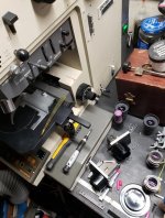
I managed to run across a neat old microscope for a pittance, planning to do some examination and perhaps photos of tool edges and a few other things. It's an Olympus Vanox AHMT or AH-BT2. This one is capable of reflected Brightfield, Darkfield, polarization and DIC illumination. Are there any fellow industrial/research microscope users around that have experience with one of these? I have a few questions about some of the techniques, prisms and filters and how they're used. Also could probably use some spare parts if anybody has any for these old scopes.

View attachment 325278

I don't know any technical details on the microscope I used to use back in the day when I ran a MIG weld department for a company I worked for before I got into tool & die, but your post reminded me of it. It was connected to a computer screen and we used it to check the penetration's depth of weld into metal. We would take a MIG welded part and cut it through the bead with a cut off wheel, Then we would soak it in acid which turned the two metals separate colors (The part would stay a metallic color while the bead turned a darker grey almost black.) then use clay to hold it in place under the microscope, then we could draw lines on the computer screen of the magnified part at the surface and at the depth of the penetration for quality checks and send screen shots to the customer with measurements...really cool stuff.

My guess is that you probably use yours to look at crystallization and grain structures and much more technical stuff, but thanks for jarring that memory anyway.
 
Here is a quick first test. Optics are in dire need of cleaning, so working on that next. Looks like everything is in great shape for the most part. Few items like sliders need cleaned and relubricated, on some of them the movements are very stiff due to the grease solidifying.

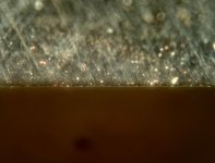
Here is a straight razor edge at about 400x optical magnification in brightfield. This is only taken through the eyepiece with my phone, so not great, but you get the idea.

20210731_131938.jpg

Same area of the blade in darkfield
20210731_135123.jpg
 
Optics are in dire need of cleaning, so working on that next.

-You're likely well aware of this but I'll add it anyway. I once worked for American Optical in field service cleaning/repairing microscopes. Coated optics may/may not have special requirements for fluids and cloths used in cleaning to avoid ruining the coating. Best to check with the mfg. for any specifics. All first surface mirrors were so fragile we did as little to them as possible. Things have likely changed since 1978 but wanted to throw that out there just in case. Nice finds, post progress, good luck.
 
Yep, thank you for making sure. I do know to be careful. I generally do a spritz first with IPA if things are seriously filthy from laying in open air and gathering dust to help wash away as much as possible. Then light swipes with an IPA soaked cotton swab, rotating with each swipe so no removed dirt/dust gets dragged back over the lens again. Fresh swab once it's been rotated all the way around. On nasty dirty lenses I go through as many as 4 double ended swabs, then use a dry one and lightly drag it across to wick up any IPA. Last but not least, if I can reach the lens to do it, a KimWipe with a dab of IPA and drag it across the lens from wet to dry. So yeah there's quite a large pile of cotton swabs at the end of the process. I cleaned the vertical illuminator and the objectives last night, things look much much clearer already.
 
Cleaning optics in this range is an art in itself.
Cotton swaps are themselves abrasive so be very gentle and of course no dirt pickup side involved.
Front surface mirrors, do not touch. spray and let drip clean, repeat.
I used to service optical comparators and this a huge opps by owners.
"Sorry but the mirror is ruined. This is 1200 dollars for a rework."..... "But it is just a mirror"... "No sir these are not like the ones in your bathroom"
100 percent guilty or many clean cotton swabs and lots of flush on a first surface. Crying all the time.
Bob
 
Yeah, best solution is not to leave precision optics lying around without being under a cover or in a closed container! But as we are aware, most don't understand that dirt can destroy lenses and coatings. I did look up the info on cleaning from Olympus but nothing there that I didn't already have a grasp on. These seem to have survived my cleaning them with no issues, everything looks great.
 
Okay, well, got into the top section of the head today. Figured I'd clean everything up and relubricate it in there - that's where some of the sticky sliders are at. Everything going well until I find some broken parts in the interpupillary distance adjuster. They appear to move the eyepieces in and out (toward or away from the user of the microscope, not center distance between them) along a ramp when the interpupillary distance is changed. Anybody familiar with such a system? Trying to figure out what that would accomplish and if it's a necessary repair. Seemed to work fine with it stuck in one position.

20210801_192554.jpg

20210801_192844.jpg

20210801_192900.jpg
 
Found a brochure describing the feature. Looks like it maintains optical path length when interpupillary distance is changed so that focus is maintained. Not super important unless you're using a camera port - in which case without this feature the parfocality between eyepieces and camera port would be lost with a change in interpupillary distance. Since I'm the only user of this microscope I'm probably going to leave it alone. I don't think I can get it apart to replace the broken pieces and free up the sticking bits without disturbing prism/mirror locations, and I don't want to go there.
 
As you've already figured, you can get everything parfocal for yourself without that broken bit. It just makes it easier and faster for others to change the interpupillary distance without messing up the tube length.

For cleaning lenses, I like "ROR" (Residual Oil Remover) a bit better than IPA. You can get three one ounce dropper bottles from Amazon for something like $20. IPA seems to smear oil around a bit more - though in both cases you want to have slightly moistened cotton, swabs, or tissue paper, make a single swipe, then pitch the oil-contaminated bit.
 
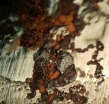
Hey Pete - or any of you others who might know - I've got the two polarizers (one fixed, one rotatable/analyzer) and polarization works but to get the bright coloration on a lot of stuff I need a retarder/waveplate, right? Is it a good idea to get a ¼, ½ and full lambda set or is one more useful than the rest? These are my first images using the polarizer. This is a little bit of surface rust at 200x optical magnification, one shot with the polarizer engaged, one without.

Polarizer:
20210810_034642.jpg

No polarizer:
20210810_034619.jpg
 
Last edited:
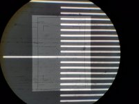
And just doing some experimentation with the different magnifications available, pretty neat stuff. This is my 10 micron calibration slide. This scope has got super widefield eyepieces, FN 26.5, FOV at 500x optical is around 515μ, with the magnifier/preview setup maxed out FOV is about 64μ but it's very fuzzy at edges so not much use, I think that's equivalent magnification of about 4,000x if comparing FOV to the 500x. It's still pretty good at a FOV of about 215μ which I think is something like 1,200x ish equivalent.

215μ FOV, 10μ graduations:
20210811_163720.jpg

64μ FOV, 10μ graduations:
20210811_163112.jpg
 
Here's a comparison of two gage blocks. One is from my "good" Mitutoyo set and the other from my Webber "shop" set.

Here's a comparison photo to see what the blocks look like by eye. Mitutoyo top, Webber bottom.
20210825_013037.jpg

First a closer look at the Mitutoyo block
20210826_023003.jpg 20210826_023024.jpg

Then a little closer view of the Webber block
20210826_023126.jpg 20210826_023158.jpg

That's 200x, then 500x on both. Click for higher resolution.
 
Hey Pete - or any of you others who might know - I've got the two polarizers (one fixed, one rotatable/analyzer) and polarization works but to get the bright coloration on a lot of stuff I need a retarder/waveplate, right? Is it a good idea to get a ¼, ½ and full lambda set or is one more useful than the rest?


The wave plates are used for measuring the change of index of refraction along crystal planes in minerals and ceramics with transmitted light. The mineral specimens are ground in thin sections to allow transmitted light imaging. The image of a single crystal is viewed using conoscopic observation with the built in Bertrand lens of your microscope . The crystal is centered in the field of view using your rotating stage. The objective turret will also have adjustments for centering the optical axis with respect to the crystal and eyepiece cross hairs.

Polarizing Petrographic Microscopes

The old Zeiss polarizing microscope was equipped with a fixed 1/4 lambda , fixed 1 lambda, variable 0 to 3 lambda, variable 0 to 5 lambda, variable 0 to 20 lambda, and a variable 1/10 lambda wave plate. The measured birefringence is used to identify crystal chemical composition using a catalog of mineral optical properties.

There is also a 1/4 lambda plate that is used for a de Senarmont compensator for quantitative DIC work. This wave plate has its optical axis aligned parallel with the polarizer axis. It is used with a rotating analyzer to measure light phase differences of up to 1 lambda. (Lambda = 5500 Angstroms)

The 1/4 lambda plate used for birefringence studies is rotated 45 degrees with respect to the polarizer axis.

The 1 lambda wave plate is also used to add color contrast to a transmitted light DIC image that would otherwise have no color. This is useful when examining unstained biological specimens.
 
Last edited:
The wave plates are used for measuring the change of index of refraction along crystal planes in minerals and ceramics with transmitted light. The mineral specimens are ground in thin sections to allow transmitted light imaging. The image of a single crystal is viewed using conoscopic observation with the built in Bertrand lens of your microscope . The crystal is centered in the field of view using your rotating stage. The objective turret will also have adjustments for centering the optical axis with respect to the crystal and eyepiece cross hairs.

Polarizing Petrographic Microscopes

The old Zeiss polarizing microscope was equipped with a fixed 1/4 lambda , fixed 1 lambda, variable 0 to 3 lambda, variable 0 to 5 lambda, variable 0 to 20 lambda, and a variable 1/10 lambda wave plate. The measured birefringence is used to identify crystal chemical composition using a catalog of mineral optical properties.

There is also a 1/4 lambda plate that is used for a de Senarmont compensator for quantitative DIC work. This wave plate has its optical axis aligned parallel with the polarizer axis. It is used with a rotating analyzer to measure light phase differences of up to 1 lambda. (Lambda = 5500 Angstroms)

The 1/4 lambda plate used for birefringence studies is rotated 45 degrees with respect to the polarizer axis.

The 1 lambda wave plate is also used to add color contrast to a transmitted light DIC image that would otherwise have no color. This is useful when examining unstained biological specimens.

Thanks for the additional information Robert, I believe that my scope uses the de Senarmont setup; it has an individual DIC prism for each objective. I believe that the analyzer has a ¼ wave plate built in. Rotating the analyzer only seems to add to or subtract from the 3D DIC effect, with no color change. I have acquired a full wave plate and will be making a slider to insert it into the light path. I observed that when I remove the analyzer and place the full wave plate behind it, rotating the waveplate shifts the apparent color when looking through both. That may be a useful thing to have at times.

I've modified my prisms a bit by removing a spring so that the prisms can be slightly translated, giving a little color range - otherwise I generally only get a monochrome (shades of white, gray and black) coloration. The tint plate will probably be a better option than prism translation, since the monochrome seems - to my eye at least - to give the best contrast.
 
I believe that the analyzer has a ¼ wave plate built in. Rotating the analyzer only seems to add to or subtract from the 3D DIC effect, with no color change. .

The false color image does require the full wave plate.

The earlier transmission light DIC microscopes used a fixed position polarizer, fixed position analyzer, a DIC prisim mounted in the condenser and a sliding DIC prism behind the objective. The DIC slider was mounted in the 45 Deg position slot above the objective The slider could be moved within the slot by turning a screw to adjust the DIC image contrast (bias retardation). The system could measure the phase shift between the specimen light beam and the reference light beam if a micrometer screw was installed and one knew the relation between the screw position and the bias retardation. The De Senarmont setup allows one to measure the phase shift in angstroms by leaving the DIC slider in a fixed position The bias retardation can be measured by rotating the analyzer. The analyzer position can be read to within 1/10 degree. The resolution of the measurement is 5500 angstroms/ 3600 divisions or 1.5 angstroms. This is a much improved setup.

If your sliders are fixed in position then you have a microscope set up for De Senarmont DIC imaging. Do not modify the sliders containing the prisms. It is a step backwards in design and you may damage the prisms.

The DIC image contrast depends on very careful alignment of the crossed polarizer and analyzer, the orientation of the 1/4 wave plate fast axis with respect to the polarizer axis and a Kohler condenser setup. The alignment procedure is detailed in the Nikon tutorial web page. It is not a quick process The procedure will be about the same for incident light DIC with the exception that there is no condenser DIC prism to align.

My Zeiss Universal does not produce the high quality images shown in the alignment tutorial. There may be some strain in the originally strain free optics and the polarizing filters are showing signs of old age.

The full wave plate produces color contrast by removing the green portion of the light spectrum. Instead of white light illumination, the image has a magenta color band shifting to blue and yellow color bands with a change in bias retardation.


Back
Top