rons
Diamond
- Joined
- Mar 5, 2009
- Location
- California, USA
It was asked before and I was looking at a old thread yesterday. Searched for it today and can't find it. There was no definite answer. Just sort of do what looks right.
The background;
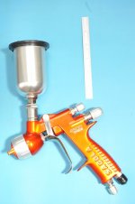
Made an adapter for a paint gun cup connection. The paint gun has a 18MM x 1.5 external thread. The paint cup bushing has a 18MM x 1.5 internal thread.
There is also a metal seal connection at the top of the paint gun connection and the inside of the paint cup.
They advertise that no plastic seals are used because the machining of the gun is so tight.


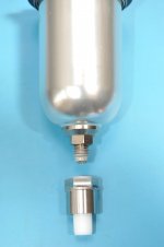
The adapter accepts 7-16-14 threaded cups. Like the plastic and metal ones made by Devilbiss.


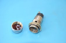
The last pic is a part that started out with diameter = ,875. The straight turned down section has a diameter = .775
The 18MM x 1.5 tap outside diameter is .715. The thread length is .325. The overall length of part is .875.
What I call the "seal area" is the part of the connection that stops paint/solvent from leaking.
The original seal area is a circular ring at the top of the metal tube on the gun. I tried to duplicate that but could not
make the internal step very accurate. So I use a cylindrical HDPE (white) piece that is forced down by my bushing part.
The intent of the force is to make the seal area inside the bottom of the gun tube.
I know this stuff is made using chrome plated brass but I've seen that peel off, including in my collection.
The part (last pic)still feels heavy like a socket. I wanted to reduce weight and diameter so I measure the original large
paint cup bushing. It is set in that plastic and I made the diameter to be .775. Now I am trying to learn what limit I can push
it and still have a working piece that is light as possible.
I think that a set of table can be made for minimum thread wall thickness using variables like pitch, overall diameter,
type of metal, length and height of thread, etc.
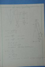
From calculations:

tan 30 = (P / 2) / H
H = .866 P
H = .866 x 1.5mm = .0511
Thread height = .625 x H = .0319
The outside cylinder surface to the inside thread will vary from (.775 - .715) / 2 = .0300 and .0300 + .0319 = .0619.
I'm looking for the limit dimension. (And for something to do)
The background;
Made an adapter for a paint gun cup connection. The paint gun has a 18MM x 1.5 external thread. The paint cup bushing has a 18MM x 1.5 internal thread.
There is also a metal seal connection at the top of the paint gun connection and the inside of the paint cup.
They advertise that no plastic seals are used because the machining of the gun is so tight.


The adapter accepts 7-16-14 threaded cups. Like the plastic and metal ones made by Devilbiss.


The last pic is a part that started out with diameter = ,875. The straight turned down section has a diameter = .775
The 18MM x 1.5 tap outside diameter is .715. The thread length is .325. The overall length of part is .875.
What I call the "seal area" is the part of the connection that stops paint/solvent from leaking.
The original seal area is a circular ring at the top of the metal tube on the gun. I tried to duplicate that but could not
make the internal step very accurate. So I use a cylindrical HDPE (white) piece that is forced down by my bushing part.
The intent of the force is to make the seal area inside the bottom of the gun tube.
I know this stuff is made using chrome plated brass but I've seen that peel off, including in my collection.
The part (last pic)still feels heavy like a socket. I wanted to reduce weight and diameter so I measure the original large
paint cup bushing. It is set in that plastic and I made the diameter to be .775. Now I am trying to learn what limit I can push
it and still have a working piece that is light as possible.
I think that a set of table can be made for minimum thread wall thickness using variables like pitch, overall diameter,
type of metal, length and height of thread, etc.
From calculations:

tan 30 = (P / 2) / H
H = .866 P
H = .866 x 1.5mm = .0511
Thread height = .625 x H = .0319
The outside cylinder surface to the inside thread will vary from (.775 - .715) / 2 = .0300 and .0300 + .0319 = .0619.
I'm looking for the limit dimension. (And for something to do)
Last edited:


