What's new
What's new

Monarch Series 61, Rebuilding for Improvement

Getting on to measuring the inside of vee way on bed, for the carriage.

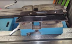
Got the lead screw reverse rod pulled off machine to make room for a mic. Don't judge my mic, it looks heinous from a PO, but it measures fine :D. With the thickness of my new tool included, I measured 2.7565" on HS side, and 2.7585" on TS side. So a .002" variance over the 88" of length of vee ways, on un-wore portions of bed.

View attachment 340439

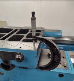
Because of the .002" variation over the length of bed, I just wanted to check the front bed rail thickness. I got about a +/- of .001" the entire length, with thickness measured at 5.238":

View attachment 340440

Feeling my numbers were good and consistent I mic-d the inner surface of vee way. As before, I marked out 15 spots, 6" apart over the 88" of vee way length. Head stock side starting at #1, this is my readings:

View attachment 340441

So the depth of worst wear area is .0105".

I was reading through your latest posts, and I have one question. Are you sure? Because I am not. Since you are using the bottom of the rails as a reference you have no real way to decide if all the wear is on the top or a combination of both. I still contend you need to buy, beg, steal borrow a Kingsway. That allows you to use gravity as the reference and it is pretty constant over 88" of horizontal travel :) But even with that, I would say your ways are fine for that lathe. The saddle is close to 24" long which makes your measured "error" less than 7 tenths per foot. I would not worry about it, it will not affect your ability to make parts with tight tolerances.
 
Are you sure? Because I am not. Since you are using the bottom of the rails as a reference you have no real way to decide if all the wear is on the top or a combination of both.

I still contend you need to buy, beg, steal borrow a Kingsway.

The saddle is close to 24" long which makes your measured "error" less than 7 tenths per foot. I would not worry about it, it will not affect your ability to make parts with tight tolerances.

I edited your quote to answer the best I can on three points.

On the first point, I'm quite sure. Many moons ago I cleaned and de-burred beds ways, including the sides and bottom. Outer flat that I can mic directly was within .0004" the length of unwore bed from the underside. Its so close, that I would presume both front and rear bottom sides are done the same way. To the micron, surely no, but even if I'm extremely generous and allow a +/- .0005" variation on each reading, it won't significantly change the assessment. And my readings are more accurate than +/- .0005".

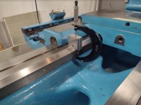
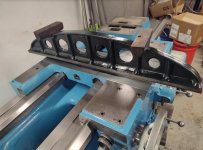
On measuring the flat way, yes I'm using the bottom as reference. But on vee way, I'll call it maybe 50%, as I'm coming in nearly on the corner. So the other half, is the side of ways, where I measured +/- .001" checking various spots the entire length on bed. Better seen from this angle:

465.jpg

I had also wanted to measure the bottom side to crown of vee, not that I entirely trust that measure, but curious to see the numbers. But the underside does not go in far enough. Its close, and looking at the end, it looks like you might be able to mic it, but you can't, mic won't sit straight.

466.jpg

Another reason I trust my numbers, is my eyeballs and fingers work a little bit too :D. Not as accurate as a mic, but I can tell the difference between .001" and .010". Before putting an indicator or mic on it, I guessed 10 to 15 thou at the heavy wear spot.

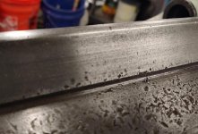
Here's a look at the low/no wear section near TS:

467.jpg

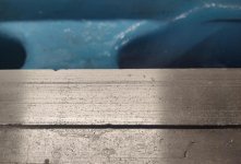
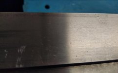
Now here's a look at the area where I'm down about .010":

468.jpg

On your 2nd point of the Kingway tool. I'm going to quote Harry Bloom. You can find that in this post:
Another New Toy

. . . In an attempt to determine the amount of wear on the inside face of the front V way, I set up the loaner King Way Alignment Tool (KWAT), using the inside ways as the datum plain. Either I'm using the KWAT wrong, or this tool is highly overrated. I could not get any repeatability checking levelness, when double checking the reading. I did not have any problems using the Master Precision Level, although it did take a bit longer. . .
Harry

I'm going to say my opinion is a little more inline with his. Not that I'm dumping on anyone, or the tool, its just not part of the system I'm doing. And without trying to make a big thing of it, I think some get so far down that rabbit hole of rebuilding, that it creates some confusion and paralysis. Where it might get hard to see the forest with all the damn trees in the way :D.

Yes, I can run the machine with ways as they are. In fact I'm pretty fair at using worn out crap. But on this I'm looking to increase my contact areas for greater rigidity, and improve the accuracy.

In dealing with the wear, I'm treating both the flat and the vee surface the same as I would set up a surface grinder. If I can contact both ends of the work piece(the bed), to the same height during a tramming operation, then I will gradually work the un-wore sections down evenly until I reach the bottom of the valley:

469.jpg

The only reason I will abort now is if I can not tram up and down the ways for a consistent reading.

P.S. If you guys could do me a favor, don't quote my posts in their entirety. It eats up pages, and makes terrible readings. Quote the portion you want to comment on. Appreciate it.
 
I edited your quote to answer the best I can on three points.

On the first point, I'm quite sure. Many moons ago I cleaned and de-burred beds ways, including the sides and bottom. Outer flat that I can mic directly was within .0004" the length of unwore bed from the underside. Its so close, that I would presume both front and rear bottom sides are done the same way. To the micron, surely no, but even if I'm extremely generous and allow a +/- .0005" variation on each reading, it won't significantly change the assessment. And my readings are more accurate than +/- .0005".

On measuring the flat way, yes I'm using the bottom as reference. But on vee way, I'll call it maybe 50%, as I'm coming in nearly on the corner. So the other half, is the side of ways, where I measured +/- .001" checking various spots the entire length on bed. Better seen from this angle:

View attachment 340446

I had also wanted to measure the bottom side to crown of vee, not that I entirely trust that measure, but curious to see the numbers. But the underside does not go in far enough. Its close, and looking at the end, it looks like you might be able to mic it, but you can't, mic won't sit straight.

View attachment 340447

Another reason I trust my numbers, is my eyeballs and fingers work a little bit too :D. Not as accurate as a mic, but I can tell the difference between .001" and .010". Before putting an indicator or mic on it, I guessed 10 to 15 thou at the heavy wear spot.

Here's a look at the low/no wear section near TS:

View attachment 340448

Now here's a look at the area where I'm down about .010":

View attachment 340449

On your 2nd point of the Kingway tool. I'm going to quote Harry Bloom. You can find that in this post:
Another New Toy


I'm going to say my opinion is a little more inline with his. Not that I'm dumping on anyone, or the tool, its just not part of the system I'm doing. And without trying to make a big thing of it, I think some get so far down that rabbit hole of rebuilding, that it creates some confusion and paralysis. Where it might get hard to see the forest with all the damn trees in the way :D.

Yes, I can run the machine with ways as they are. In fact I'm pretty fair at using worn out crap. But on this I'm looking to increase my contact areas for greater rigidity, and improve the accuracy.

In dealing with the wear, I'm treating both the flat and the vee surface the same as I would set up a surface grinder. If I can contact both ends of the work piece(the bed), to the same height during a tramming operation, then I will gradually work the un-wore sections down evenly until I reach the bottom of the valley:

View attachment 340450

The only reason I will abort now is if I can not tram up and down the ways for a consistent reading.

P.S. If you guys could do me a favor, don't quote my posts in their entirety. It eats up pages, and makes terrible readings. Quote the portion you want to comment on. Appreciate it.

Fair nuff' :). After all, it is your lathe. Looking at the close-ups I fully agree with you. No point in me being a Monday night quarterback. It will be a costly regrind, or a long-time scraping job, 11 thou is definitely machining territory. Does that 61 have flame-hardened ways? If not you could have someone plane the bed then scrape it. Might save you a few coins
 
Texas, if things take an unexpected turn for the worse I have a 54" center bed that has been outside, but appears to have been in very good shape before the rust. If you were to need it, I would clean it up and qualify it to check the condition.
 
Getting around to making the other two tools. These will also be something of a vee block form. One for carriage vee way, one for tail stock vee way:

474.jpg

Here you can see I have the basic vee form cut out. But I don't want interference from potential high ridges at either the top or bottom of the surface. You can see I marked black dots for what I will mill out:

475.jpg

Got both finished, and they came out pretty fair as well:

476.jpg

Here's the one for the carriage vee. You can see the contact surface will avoid both top and bottom ridges. Now I can mic from underside of ways to the top of the block. Purpose on this carriage vee tool is to gauge how much improvement after grinding takes place, by comparing before and after numbers.

477.jpg

The tail stock vee tool. Same in principle, but this I really want to know the numbers before I grind. Intent is to use tail stock ways for my sled/tram. I know I have a drop on the flat way, which I will need to address. But I want to know if I have a drop on the vee as well.

478.jpg

I'll be measuring 6" increments the entire length of bed with these as well.
 
Instead, I expected to make us of one or more of:

- near and away vertical surfaces, extreme inner or outer, 'tween ways only "maybe".

- UNDERside flats, outer NOT inner (TS clamping damage) .

- NON working flats.. .. between "working", hence WEARING, vee or flat ... stoned of burrs.


"Priorities"

Ever' body has their own ones...

I appreciate you trimming my quote down, really. Thanks.

Good points. And some stuff you, I, and Rabler had been discussing in Idacal's thread here:
monarch 60 series ideas

While I have been planning to use the TS base as my main building block for the sled, and still do, the sled is going to a bit heavy and extended a bit as well. Currently those extensions will allow me to place outriggers of a sort off the top of TS base.

While I don't have it 100% sorted out yet. Plan has been to use outriggers on the non working flats top side, and potentially using the sides of bed as well. Could be I need to accommodate more, I just didn't get that far yet.

I've had other work this weekend so didn't get the numbers yet on the vee's, hopefully tomorrow. But as an example. I have a low spot on TS flat way. Outrigger set to just touch down where I'm on unwore section. Then as sled is pulled over the low section, the sled will ride on that outrigger until TS base reaches the next unwore section.

The TS flat is wore due to the saddle's short flat riding close to it and having garbage drug over it. The TS vee does not sit as close to the saddle though, so less or no damage there. Once I measure, I'll know for sure whether the vee side needs to be addressed as well.

While I am in that painful part of the project where: "I just want to be done. . ." Also doing it is a priority for me. I want to know if I can or can't, and answer that question.

With other long projects I also felt that pain a bit. But once done that evaporates, and I know I have something damn near bulletproof.
 
Getting on to measuring.

A point I had in the last post about the tail stock ways. The carriage short flat rides close to the TS flat way with maybe a .010" gap. Debris caught under can get drug back and forth and mark up the TS's flat way. The TS vee way on the other hand has a lot of clearance:

484.jpg

And looking at the TS flat way, we can that scoring:

485.jpg

And looking at the vee way, in same wear area, looks much better. I was guessing minor wear, maybe a couple thou:

486.jpg

Getting on with measuring:

487.jpg

Turns out the drop on the TS vee way was more than I expected. Pretty disappointing, but I'll have to do something about it:

488.jpg
 
Running the same sort of test on the carriage vee way.

489.jpg

The numbers look slightly better than expected. The tool I made, though not riding on upper or lower ridge, still has a pretty fair contact surface. So I'm probably still riding some higher lines in the scoring to surface.

Really not a problem here. For this I mostly wanted numbers to compare to after grinding:

490.jpg
 
I doubt if the tailstock vee way is as bad as you described. The bottom (clamping) surface has been worked hard by the tailstock clamp, even more so if the tailstock did a lot of sliding while clamped from drilling pressure. The carriage way looks better because there is only minimal clamping from the carriage clamp, and the carriage is retained by non-contact keepers rather than contact gibs.

Can you make a gage that will ride in the planed area between the ways?

There may be something to your point on wear to the underside of bed from the clamp. But at best its maybe 10% of the wear numbers I posted. Only decent visuals are from the end of bed. But using finger tips and finger nail along the worst wear section, I don't feel anything. Also I went to get more pics to explain.

First, the tail stock is in the area of 400-500 lbs. All that weight is straight down, and dragging on ways when slid.

Next, this TS has a quick release for locking it down:

492.jpg

When released, it opens a visible gap between bed and clamp. It doesn't drag on the bed:

493.jpg

And the bed clamp is no joke, I want to say maybe 8" of clamping surface on each side. You can see the bed clamp here leaning on the orange bucket:

150.jpg

I wouldn't think a gorilla is going to move that 500 lb TS when the bed clamp is locked, drilling or not.

Also the previous post where I showed TS vee wear was from front side of lathe. This time I went to the rear side where I could feel the ridge better with a finger nail. Zooming in, its more visible that the other pic. This spot looks more horrid due to some water spots:

494.jpg

Moving to the side a little from the last pic. Note the visible ridge at top and bottom:

495.jpg

I am very big at getting numbers and evidence to prove one way or another. But making a gauge to check the underside of bed is not going to dramatically change the direction I'm going. Priority was to know if I needed an outrigger on that side for the tram/trolley/sled thingy, and I do.

Secondary was to figure out if I should grind TS vee way as well, and I might. But it will be last in line if I do.
 
I see you have the single speed tailstock, that won't develop as much thrust. My machine has the two speed tailstock, and even with both tailstock clamps locked drills over 1 1/4" will move the tailstock. If I need serious drilling I use a crutch behind the tailstock.

On your measurements for the carriage vee ways, if you can just remove the original material at your positions 1,2, and 3 to match the positions 4-6 and leave the rest of the bed mostly alone you will greatly increase the usefulness of the lathe. If you are successful getting the headstock rise out, then try to ease the abrupt rise at 7-9 to taper into 11 or 12. The difficult part is its easy to measure in the vertical plane, but its the horizontal plane that causes the most change in the workpiece diameter.
 
I see you have the single speed tailstock, that won't develop as much thrust. My machine has the two speed tailstock, and even with both tailstock clamps locked drills over 1 1/4" will move the tailstock. If I need serious drilling I use a crutch behind the tailstock.
I have so many questions ! :D

Is that on the 612 ?

I'm curious if the bottom of TS is still cast iron, or been redone with turcite or mogilice. I saw some guys had some slippage with those materials on TS.

If no, I wonder how good the contact area of TS base to bed way is. Also, if your bed clamp is like mine, there's some adjustment on the angle of contact, and how it locks.

And the drilling operation, if 1-1/4" and bigger, are you going right for it, no mercy :D, or stepping up in size along the way ?

On a two speed TS, is it something you shift, or is it more of an automatic gear reduction depending on load ?

On mine I've placed the order for the bronze I'm using on repairs. Most I'm using is c932. But for the TS base I bought c954 which will be a little less slippery. We'll see how it goes.
 
Yes, on a 612. The lathe has been rebuilt, but I don't know what is on the bottom of the tailstock. There are two overhead crane sized steady rests between the tailstock and hanging the edge over the end of the ways. It cranks like it is iron on iron. The bed clamp is much different than yours. Both clamp handles come out the back of the tailstock. One clamps the rear clamp directly, the other clamps the front through a linkage. Yes, I typically drill larger holes from solid, no mercy. Even if I predrill to web size, the predrill hole is often to short for the full depth of the hole. The 2 speed has a gear shifter on top of the tailstock, no automatic.

I do have a spare, somewhat rusty 2 speed tailstock with the integral bearings in the barrel.
 
Alright, getting down to it.

I yanked feed and clutch rods. And prepped for yanking qcgb off. As mentioned previous, the lead screw bearing cap bumps up on the bed way before being able to get out. So some care and patients is needed for getting qcgb off:

505.jpg

This time I grew a brain and marked the teeth for lead screw reverse bevel gears. They mate between qcgb and headstock. With them marked, my timing for the lever position will be right the first time :D.

506.jpg

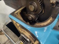
Again use care on gears and housing on left end as you begin to slip the qcgb off.

507.jpg

I went ahead and yanked headstock back off, and the upper half of tail stock:

508.jpg

Using a trick I saw from some 10ee postings, I laid 2 x 6's across the chip pan. Makes for good temporary storage of TS upper and taper attachment:

509.jpg
 
I adjusted my precision leveling of bed slightly using the clean surfaces under headstock.

From this point I will be dividing my attention in two areas simultaneously. If I get tired or bored in one area, I can procrastinate by moving to the other. :D

Those two area:
1. TS base and sled/trolley for grinder. I'll be getting the contact surface flat on TS base to use as the base building block for the sled/trolley for grinder. After grinding ways, I will mill and add c954 as the ways bearing for TS. For now, I just want good contact.

2. Saddle and cross slide surfaces. Before grinding ways I'd like to have this mostly sorted. Problem being I can't trust surfaces from the bottom bed way of saddle to the top surface of cross slide. Decision made. I'll be working top down to get surfaces flat and level. So cross slide first, then dove tail of saddle. With those areas flat and level I will adjust any milling and working of bed way surfaces of saddle after bed is ground, to match the top sides level surfaces.


After re-leveling bed. I checked TS base. I was .010" low on vee way side, and HS side:

510.jpg

Confirmed by mic-ing it:

511.jpg

Just an fyi, for any interested, the way surfaces under headstock were not scraped in, they were ground only. If any scraping was done, it was to the HS itself. Except for some water spots in some areas, those surfaces look really nice:

512.jpg 513.jpg 514.jpg
 
Moving on to check contact surfaces.
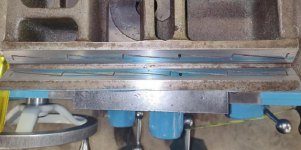
I'm using a wood stain type spongy type roller and paint tray found in Home Depot, Lowes, etc. And Canode die spotting ink from American Rotary Tools. I like this as it will not permanently stain me or the machine the way prussian blue will:

515.jpg 516.jpg

Checking contact at TS end of bed first. I went slightly heavy on the ink:

517.jpg

My contact area on flat way was amazingly terrible:

518.jpg

Vee way contact better, but not great:

519.jpg

Seeing this surface contact, I can really understand gbent's comments on the TS pushing off when locked down.
 
Update from my last post, I also blued and checked TS base on head stock surface area of bed ways. Pretty close to the same results in the last post.

Moving to check cross slide. I had better and more detailed pics. But apparently my phone ate them. I do have some from what i was doing which I'll get posted here.

I blued up the dovetail on saddle, way surfaces and top of dove tail. Laid the cross slide on and checked. I was basically contacting on the four corners of way surfaces, Like the cross slide was bowed upwards in the middle.

I yanked it off and first used a shorter straight edge to check it. The straight edge not as long as the cross slide. The blue markers you see here are the full length ends of that straight edge.

520.jpg

Though that straight edge was shorter it confirmed the cross slide was warped upwards.

I don't have the pic of the results, but I used this straight edge on the cross slide way surfaces. And the contact points were at the very ends, further confirmation it was warped.

521.jpg

I then flipped the cross slide over to check the top side. Not highly visible in this photo, but all the contact was in the center on cross slide:

522.jpg

Knowing I'm going to machine the surfaces, I wanted to measure the thickness of both way surfaces to the top of cross slide. Using those numbers I might adjust its mounting as I set up to machine:

523.jpg

The notes on the measurements I took:

524.jpg
 
I forgot, and wanted to stick feeler gauges between the straight edge and cross slide. So I figured I'd blue it again for the pics.

Not super visible in pics, but here it is, contact out on the very edges of ways surfaces:

530.jpg

Zooming in on each side for a better visual:

531.jpg 532.jpg

Sticking feeler gauges in, I can get a .007" on head stock side, and .004" on TS side:

533.jpg
 
Looks like a candidate for may material. I used Multifil on mine when it was .012 low.

My original plan was just to clean, lube, and do minor repairs. Since I've reverse course on that, I'm going to machine the surfaces flat.

For the cross slide, machining the surfaces will also give me the chance to "pretty" it up a bit too. Top side has a bunch of work related dings:

522.jpg

And since it is bowed upwards, I'll machine top side first to get it flat. Then flip it over to do way surfaces. Also needing attention will be that inside surface that rides over the dovetail. I need to take a little off there too, so as to not contact the dovetail. Harry had some thoughts on that as well, with the T/A drawbar:
Another New Toy

In thinking about what he wrote, I want to mount taper again, and the drawbar, just to look and measure. In the end, I think I will choose his course. Besides the obvious, the top of my dove is mostly pretty good and straight. It will be surface i'm going to reference for leveling saddle. Just need to scrape some high spots down, but a quick check, the top side of dove tail is pretty good.

I also want to machine top side of saddle's flat surfaces. Not work related, someone thought those surfaces made a good anvil

535.jpg

If that person is out there, I hope they have lived every day with uncontrollable explosive diarrhea, with bouts in front of pretty girls. Besides the saddle, they like to beat on the bed at TS end as well. I'll be looking to get that out too:

536.jpg

Good news, I got my bronze order in. C954 for TS base, for way surface. And c932 which will be the saddle way surface:

537.jpg 538.jpg


Back
Top