What's new
What's new

Multi Start Worm on a CNC Lathe

Vishrut

Aluminum
Joined
Dec 18, 2013
Location
India
Hey folks,
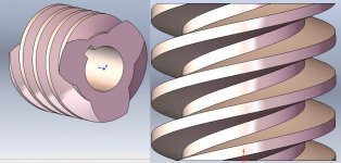
I need to make few Multi Start Worm threads on a shaft.
Intend to do it in my Cnc lathe, Fanuc control.

Pitch 20mm, Lead 60mm, 3-start thread.
OD is 90mm and ID is about 60mm.

Depth is huge and I'm wondering if can do with some macro programming.
I don't think form tool will be able to bear the cutting load. Material is Bronze.

Is there option in Fanuc where we can rough and final using two different tools?

Request programming help.worm.jpg
 
Have done such. I find it works much better for me to write each pass manually, in what is G33 on a standard-code lathe. That gives you much more control of the chip thickness as depth increases. Your first part wil probably not go perfectly :)

With three starts though, that gives you three tries to get it all perfect.

I only used two tools - hand ground HSS, one did the forward flank, then the second to finish the rearward flank after the thread was roughed.

Once you get it running, it's kinda fun. Hope you plan to use a tailstock ? You'll get some hefty side load and bronze is tough stuff. MAYBE use a third tool for roughing, since you'll want to keep the finishers sharp. Did I mention that bronze is tough ?
 
Hi,
Didn't know that you can use multiple tools in threading. How do you ensure correctness of offsets ?

Yes, I'll be using tailstock.
 
It can be done, it will need to run low rpm to keep up with the lead. I would use a macro with G32 and use a full radius grooving tool to rough it out, then a really small step over to finish. I run crane hoist drums this way and they come out way quicker than it sounds.

But I would personally not even try it on these. Just find a local thread grinding house. Bronze they should have no problem grinding from solid for a reasonable price. I would guess under $100 each depending on qty, more than 4 and I’d guess even less

This same method works fine on parts like op's except with a plain grooving tool instead of a full radius one.

I use this method quite often, but it's easy for me because my CAM supports it directly.
 
Hi,
Didn't know that you can use multiple tools in threading. How do you ensure correctness of offsets ?

Yes, I'll be using tailstock.

copied from this book ..

Using Two Tools
If the threading job is extensive, the threading tool would wear out very soon. In such a case, it might be more economical to use two different threading tools—one for roughing and the other for finishing. Even a slightly worn-out tool can be used as a roughing tool which should be used for all the threading passes except the last 2-3 passes, for which a finishing tool may be employed. Even a different RPM for the finishing tool might be used, if desirable. This would reduce the cost of tooling to a great extent, and at the same time, the quality of machining would also improve.

Shift in Threading Helix
A serious problem with using two tools is that, even if the start points are kept same, once the RPM and/or the tool is changed, the machine starts following a different threading helix which will spoil the thread. To overcome this problem, the operator will have to experimentally determine the axial shift of the helix when the second tool is used, and add/subtract (as appropriate) this amount to/from the initial axial position of the first tool, to determine the correct axial start position of the second tool. For example, if the first tool starts machining from Z = 10, and the helix of the second tool lies 1 mm to the left of the helix of the first tool, the start position of the second tool should be changed to Z = 11, to make the two helices coincide. The amount and the direction of the shift (left or right with respect to the helix formed by the first tool) can be found out by conducting a simple experiment, described next.

Measuring Shift in Helix
Consider the case of an M30 thread, for example. Take a workpiece of 30 mm diameter and run the following program with the first tool:
G00 X35 Z10;
M03 S200;
G92 X29.9 Z–10 F3.5;
This will just scratch a thin helix on the workpiece. Apply some color to it to differentiate it from the second helix to be made next. Now, run the same program with the second tool, without unclamping/re-clamping the workpiece. Another helix will be made. Using some accurate measuring device, such as a tool-makers’ microscope, measure the shift between the two helices, and also observe the direction of the shift.

Note that the experiment described above will need to be repeated for every outer diameter and every RPM. The RPM during the experiment must be the same as that in the original program. However, the RPMs for the two tools can be chosen to be different, if desired. Also, the entire threading operation, i.e., roughing and finishing, both should be done in the same setup. Once a partially threaded workpiece is unclamped and re-clamped, the same helix is not guaranteed in further machining. This also means that rework on a thread is not possible using conventional methods, once it is unclamped.
 
For a multi-start thread, we either use the Q-method or just shift the start point by the pitch distance.
 
What others have said and I will add... Make sure that your clearance angle on your tool clears the helix. On that lead it might be worth it to draw it out and see if your tool will clear when cutting.
 
copied from this book ..

Using Two Tools
If the threading job is extensive, the threading tool would wear out very soon. In such a case, it might be more economical to use two different threading tools—one for roughing and the other for finishing. Even a slightly worn-out tool can be used as a roughing tool which should be used for all the threading passes except the last 2-3 passes, for which a finishing tool may be employed. Even a different RPM for the finishing tool might be used, if desirable. This would reduce the cost of tooling to a great extent, and at the same time, the quality of machining would also improve.

Shift in Threading Helix
A serious problem with using two tools is that, even if the start points are kept same, once the RPM and/or the tool is changed, the machine starts following a different threading helix which will spoil the thread. To overcome this problem, the operator will have to experimentally determine the axial shift of the helix when the second tool is used, and add/subtract (as appropriate) this amount to/from the initial axial position of the first tool, to determine the correct axial start position of the second tool. For example, if the first tool starts machining from Z = 10, and the helix of the second tool lies 1 mm to the left of the helix of the first tool, the start position of the second tool should be changed to Z = 11, to make the two helices coincide. The amount and the direction of the shift (left or right with respect to the helix formed by the first tool) can be found out by conducting a simple experiment, described next.

Measuring Shift in Helix
Consider the case of an M30 thread, for example. Take a workpiece of 30 mm diameter and run the following program with the first tool:
G00 X35 Z10;
M03 S200;
G92 X29.9 Z–10 F3.5;
This will just scratch a thin helix on the workpiece. Apply some color to it to differentiate it from the second helix to be made next. Now, run the same program with the second tool, without unclamping/re-clamping the workpiece. Another helix will be made. Using some accurate measuring device, such as a tool-makers’ microscope, measure the shift between the two helices, and also observe the direction of the shift.

Note that the experiment described above will need to be repeated for every outer diameter and every RPM. The RPM during the experiment must be the same as that in the original program. However, the RPMs for the two tools can be chosen to be different, if desired. Also, the entire threading operation, i.e., roughing and finishing, both should be done in the same setup. Once a partially threaded workpiece is unclamped and re-clamped, the same helix is not guaranteed in further machining. This also means that rework on a thread is not possible using conventional methods, once it is unclamped.
wtf ? Have you ever done this ? Jesus.

The thread he decribed is .625" deep.

This is the problem, not whether you offset the start point by one pitch or however you want to do the programming or whatever. That's a deep thread with a lot of sidewall.

I don't believe a part-off or grooving tool will work well in this case. Sandvik used to make a small full-radius circular tool at (I think) 6 mm that might be small enough for roughing this out ? But you'd have to chop off part of the support blade because the bottom is going to drag on the helix. Most likely not worth it.

Otherwise, it's time to grind some a HSS tools.

Maybe someone is good enough with macros to control the tool extremely well between passes, but in my experience actually doing similar jobs, a sacrificial piece and close observation with G33 (that's the actual standard, I do not remember what the Japs use) with individually written paths is the easiest method to modify for when pass #5 is .003" too much, but pass #2 could take a heck of a lot more and pass #7 is just starting to chatter ...

Maybe some of you are good enough to predict that stuff, but not me, so I have to go with a method that is accurately and easily modifiable in practice.

This is actually a pretty simple task, after you get through the trial and error part.

Lead angle on OP's thread is 13°25' - a typical grooving insert will have 7° of side clearance angle, so another 7° of tool tilt, some front rake ground on the holder, and you're good to go. Tilting the tool does mean that the floor/minor dia is not perfectly flat, but that's not usually such a huge deal. Centre height needs to be set such that the trailing edge (depending on tool orientation - right hand thread and right hand tool means the tool is tilted forward, so the trailing edge is higher) is on centre height, with the leading edge below centre by however much the tilt dictates.

It works best/easiest if the grooving tool that is slightly more than half the width of the threadform at the top and slightly less than the full width at the bottom (threadform allowing), that way you can progressively cut alternating flank with very small DOC (less than the corner radius of the grooving tool, so it's basically skiving) to generate the thread.

Like I said previously I use CAM to generate progressive threading passes for this kind of thing now, but have long handed it in the distant past before I had that option. For a uniform geometry like a typical threadform, it wouldn't be too hard to write a macro for it.
 
There was a day not long ago that worms were made on a thread mill. A mill/turn would do these nicely.

I thought of this earlier, but sadly only have 4th axis on VMC. Neither 5th axis, nor millturn multitasking one.
 
There was a day not long ago that worms were made on a thread mill. A mill/turn would do these nicely.

Thats still the quickest way if you have one. I could threadmill that bad boy in 1 cut per lead guessing 6 minutes per pass. And cut them all day long without tool wear or chatter. But to the OP I assumed if he had a Pratt or Lees Bradner he wouldn’t be considering doing it on a cNc lathe. I make thousands of 2” diameter worm shafts every year, cNc turned then threadmilled on a Pratt and whitney model C (not the lathe version).

Also a live tooled lathe with a c axis can only yhreadmill like a true threadmill with a really expensive head that can rotate the cutter axis to match the helix angle.


Back
Top