What's new
What's new

My Very Own Monarch 10EE Restoration

Okay, I think I've fully ruled out the motor and the field control circuit. I hooked up a DC power supply to the A1 and A2 terminals of the DC control box. Then, with the WIAD energized and the spindle control in neutral, I ramped the voltage on the power supply to 30v and got about 150 RPMs out of the spindle. It picked up smoothly and quietly. All the electrical clashing that happens when I normally energize the spindle was gone. All I can do is look at the armature control circuit, but I've already replaced everything but the transformers, wires, and the tube sockets. I swapped every control tube for spares to see if the behavior showed any variance and it didn't. Presently the SCR's sit-in for the C16Js, the capacitors have all been replaced except the tiny micas, and the main speed control pot exhibits a smooth and linear and smooth change in resistance across both sides.

I'm going to proceed with a thorough rewire of the WIAD as soon as more MTW shows up. I am SUPER open to other things to try before I start pulling apart this rat's nest of nasty old wires.

Shared album - Tim Bogdanof - Google Photos
 
Well.. despaireth ye not. At least you have a worthy CHALLENGE!

That's the kind of encouragement I need right now. Working on this thing has become... not fun anymore.

I had the same inkling about the series field too. I'll go ahead and try cutting it out of the circuit. I'm also going to borrow someone's FLIR camera and take some video of the WIAD while it's running and see if I can find any problematic connections/wires that way.

Have you tried watching the DC cabinet - specifically the relays - while this is happening? I have a vague memory of this sort of problem being caused by one of the relays being misadjusted.
 
It’s fixed! It turned out to be grid-circuit related. Apparently, when I replaced the two resistors at the anode of the thyratrons in the Field Control circuit, I mismatched some of the connectors at a terminal bar. When I originally performed this operation, I went ahead and replaced some of the wires because many of them looked really terrible. Some of these wires were connected to the Grid transformers. Specifically, I had switched one of the primaries of the field grid transformer so it was connected to A25 instead of A24. Concurrently, the secondaries of the armature grid transformer were swapped so they were driving opposite thyratrons.

This came at the end of a marathon repair session where I was giving myself until Friday to figure it out or sell it as-is. I lost my shop in the middle of this and was under a tremendous amount of pressure to get it painted, fixed, sold, and out before the end of April; all while trying to ignore the invisible gun I keep feeling pointed at me that is the COVID-19 pandemic. At around the second hour, I resolved to trace every wire in the serial-matched manual to what my machine had. I started with the compensation circuit because those were among the first wires I replaced when I started the re-wire of the system and thought I had screwed up there. I checked every wire this way and it revealed NOTHING. The secondaries of the grid transformers on the schematic I used are not labeled and the associated voltages were all within 5% when I measured them.

Time to pull my ace in the hole. Russ sent me a PDF of a the factory wiring schematic that shows the wiring topology of the WIAD. It difficult to read, so I went ahead and put the graphic in Inkscape and colored all the traces to make it easier to follow the junctions. At the same time, I labeled the resistors on the wiring diagram and the schematic to give myself one thing to hold in my head. I’ll upload it when I figure out how to shrink the file size into something that PM will accept but is also legible. I started at the top and immediately noticed the problems with the grid transformers. It fixed everything.

I put the entire thing back together and wiped it down. I put the craigslist add up right away and it was gone in less than 24 hours for my asking price.

After I found the problem I came back to PM and found some threads that described similar problems and connected them to the grid transformers. If I had managed to find this post by Leigh, it would have solved everything. Oh well! For the record, anyone experiencing a drum-like sound when the motor is under power needs to start with the grid-transformers.

What an odyssey! I’m so glad I followed through and was able to fix this, otherwise I would have spent the rest of my life wondering what it was. Thanks for tall the help guys, I really doubt I ever would have been able to solve without all the help. Special thanks to Russ for all the super-responsive PM help. That wiring diagram ended up being the critical tool for me.
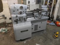
IMG_20200324_172059.jpg
 
Last edited:
Well.. thank YOU for seeing it through, for working so diligently to "inkscape it out" and for giving the lot of us "closure" as well as a refreshed reminder as to how thorough one must be - documenting our work-wise - lest we get off on the wrong foot and end busier than a one-legged man in an arse-kicking competition!

:)

All's well that ends well. I suspect the NEW minder on that 10EE's "duty roster" will check-in here in due course!

Poor lad probably hasn't yet twigged to the reality that you don't exactly "own" a 10EE.

A 10EE only rents itself new gigolos in line of serial monogamy succession.

:D

I guess I'm the next gigolo then :). After purchasing from MechanicalMan and having the lathe moved an hour away it sat for a few weeks until I was able to hook it up to 240 in my garage. It started right up but would plateau at about 3k so I started the drive tuning procedures and the troubles began...

Long story short, the grid transformers behind the tubes and the 1600 ohm resistors in the DC cabinet were on their last legs and gave out within a few minutes causing the spindle to intermittently turn on and refuse to go above base speed into field weakening. The ceramic on the 1600 ohm wire wounds was crumbling away causing the contactors to flutter. The grid transformer wires also fell out completely when manipulating the phase of the secondaries. I replaced the pair of 1.6k resistors with modern 1.5k wire wounds and the original Stancor A-73C grid transformers with Hammond 124Bs, all working a treat so far. The Hammonds are $48 each but readily available unlike the originals which occasionally pop up on ebay.

After a lot of continuity checking and testing the last bug was faulty wiring between the spindle control field pot and the terminal panel in the drawer. Somewhere in the belly of the machine the field potentiometer wires are shorted so the field pot value doesn't change with the knob exceeding half speed. I removed the pot and wired it directly to 13 and 15 at the terminal block and it's all working now. Next weekend I'll put the pot back in place and replace the faulty wires, post a few photos as well.

Not the journey I was hoping to have when the lathe was in running condition, but I expected some issues and learned a ton about how it worked by going through the repair process. Many thanks to MechanicalMan for extensive phone support and even popping over for a day to troubleshoot in person!
 
Guys, restoring this lathe made me realize that deep down, I'm just an adult man who likes making music videos about his petty mechanical bullshit.

So here it is!
YouTube

The video is on a timed release, so it won't be viewable until after 6:30 pm PDT when the "curtain goes up" so to speak.

Thanks again PM community!


Back
Top