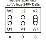
Hi All,
Thanks in advance for reading this post and providing any guidance.
I am working on a friends newly acquired 24" bandsaw and I have been unsuccessful at getting it wired back into operation after the motor was removed and serviced.
It has a star, delta switch and a separate overload protector switch.
It also has a power actuated brake built into the motor, this is working properly.
I can wire the star power wires with the delta wires disconnected and the motor runs, and runs in the correct direction. There was a photo of these wires before the motor was removed so I am 100% sure that these wires have been restored to their original position.
I can wire the delta power wires with the star wires disconnected and the motor runs and in the correct direction if I wire this in a sequence that works for this. eg 321, 213, 132.
The problem is that with both the delta and star wires connected, the overload protector immediately triggers as soon as I try to run the motor by turning it on in the first switch position (star).
I admit that I am not experienced with wiring machines of this type, but I do have electrical experience and I can run tests if anyone knows what might be wrong here. I believe I have tried every forward running combination of the delta wires but the result is always the same, the overload protection trips.
The switch wiring is a bit complicated and I don't know what the internal connections are supposed to be in the star and delta positions.
Thanks again for having a look.


