What's new
What's new

Need Help. Ecoca EL4610-e W/Mitsubishi Meldas 64 control

No idea which folder would be best. I've only ever worked on one MeldasMagic control and that was close to 25 years ago. I have no memory of how files were stored and backed up on that model.

Fortunately most operational functions of the Meldas series were very similar in that era so most of what I know from my 27 year old Meldas 50M is very similar to how you do things on the MeldasMagic.
 
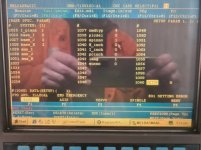
Unfortunately neither of these methods worked. This was with the original NCback folder, the one I believe has been messed with. Ran out of time to reload with the other NCback folder. Both methods returned the same error message. I also noticed the 'reverse format' displaying the word SETUP at line 1060. This is not new, it's always been like that. Just didn't pay it too much attention until today.

First method

20220412_125451.jpg


Second method

20220412_125817.jpg
 
Update, this seems to have cleared the Z56 alarm. I picked up a few new errors to do with conflict in parameter settings, figured this would come up. I'll go through the parameters as soon as I get a chance. Now that I'm back at work I literally get 20 minutes a day to work on the lathe. As a point of interest the alarm is S02 INIT PARAM ERR 2219. It is out according to my parameters manual.

I still have the Z70 ABS. ILLEGAL 0001 Z alarm. At some stage I will need to deal with this and I think it might become a problem. None of my manuals does give specs for ABS or machine zero. I can't seem to get any reply out of Ecoca (if they're still in business), so I think my next best option is to find some kind soul who has the same lathe and ask them.
 
Once you enter the servo parameters the S02 alarm should go away after a power cycle.

The Z70 alarm means that you need to set the absolute encoder position to the physical machine position. The position for that is determined by the machine builder. If you can't get that from the builder, then you'll have to fake it. Typically for a lathe you would dial X into the spindle centerline then move back the dimension determined by the builder then origin the axis. Send me an e-mail address by PM and I'll send you a generic procedure for setting the origin. You will have to determine a position for machine zero.
 
Todays update still brings no joy.

At first I tried to cheat and reload the old parameters to get rid of the S02 alarm, this brought back the Z56. Start over. Got rid of the Z56 and I'm back to where I was before. Manually entered all the parameters from the book at the control panel, restart system, no Z56. When trying to save the parameters a popup said 'the file already exists, overwrite it?' I clicked 'YES' being as I already have backups, and popup says 'file does not exist'. Still have the Z70 001 & have picked up an M01 006, had the M01 alarm before and cleared it no probs. But at this point I was done for the day.

Researching further into the Z70 alarm I realized I have another issue, one that might stop me fixing these alarms. I can't move the axis with the controls at all, figured this was because of the alarms. I read that in setting the absolute position I need to touch off on a machine stop, load the axis up, then move to the next grid point. I haven't had the axis or spindle moving as of yet (purchased machine not working), so at this point I don't know if the servos even work. Is there some sort of 'test mode' I could use to see if I am chasing my tail?

I can manually move the axis by rotating the pulley, and the encoder is responding to change. Also the drives only show alarms relevant to having lost mem battery.
 
As far as I can see there is only physical limit switch for detecting saddle to tailstock collision. I could be wrong, but I've not found wiring to support the axis either. I'll look at the electrical manual again tomorrow to be sure.
 
If a builder chose to not install hard overtravel switches, it would only require a jumper to bypass the circuit.

This helps illustrate how much influence the machine builder’s choices affect the behavior of a CNC control. A quick check of the wiring diagram should be all that’s needed to verify how the hard overtravel circuit is set up.
 
I'm leaning towards an issue in the settings. I'm pretty sure last time I reloaded one of the files and it went away. Also, the only thing that has changed between the alarm being there and not being there is software related. And none of the axis have been moved. I've only moved them once a week ago by rotating the pulley to make sure they moved freely and the encoder was working/registering.
 
The electrical manual shows that the overtravel limit switches are optional (see pic.) This brings up another question which I think is relevant to this current state. Should I have the machine set to DOG-Type? Not sure what it's set at now but I can check next time. I am assuming as I have factory parameters set it should be ok.

(2) Selecting the zero point initialization method
Select the zero point initialization method with the following parameter.
#2049 type 1: Dogless-type Machine end stopper method
2: Dogless-type Marked point alignment method
3: Dog-type


Screenshot_84.jpg
 
Was worried you might say that. I can't find any marks, I have asked around even asked Ecoca. No luck. None of the manuals I got with the lathe have any info on this setup either.
 
Usually there are no marks, but measurements from known positions. On a lathe, X is usually found by dialing in an ID holder at CL then moving back some distance determined by the builder, then origin the axis. For Z it is usually a distance measured from the spindle nose. If the builder can’t provide that info you’ll have to make up your own reference point. The downside to that is that the soft overtravel values set in the parameters will probably not be right and you’ll have to determine and set your own.


Back
Top