What's new
What's new

New Featherweight Angle Plate in the Drawing Stage. Metrology and Setup Versions to be Made

dgfoster

Diamond
Joined
Jun 14, 2008
Location
Bellingham, WA
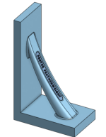
I am letting folks know that I am in the process of designing an angle plate about 11" high with a 6" base that will be available in two versions. One will have heavier faces with plenty of "meat" for keyways or bolt holes so that the end user can customize it or a pair to their needs. The other lighter version will have thinner faces more suitable for use as a metrology tool. Since the plate is still in the planning stages and nothing has been committed to pattern making, changes are relatively easy. All I would need to do is to revise the CAD drawings I am making. Once I feel confident of the design, I will be 3-D printing PLA Filament patterns and casting them in high quality cast iron. Forrest Addy has been critiquing right along as the plans have been evolving. So, don't be reticent about making suggestions for improvement. My goal is to produce very solid and stable plates that are also, consistent with other Featherweight designs, aesthetically pleasing and light in weight as is consistent with the most important aspect---good function.

Here are a couple pics of where this stands now. But if you want to REALLY see the drawn part, go to the no-hassle linked view within Onshape----no need to join. THere are several tabs in the linked work space. Just leaf through them. Spin and magnify the part, etc.

Onshape link to CAD drawings

3/4 view:

1669090419561-png.380160


Side View

1669090499576-png.380161


Drawing a Core that will be converted into a core box.

1669090844387-png.380163


Core From another viewpoint:

1669090914849-png.380164


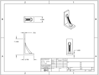
For those that like drawings:

1669090622765-png.380162


And I am finally getting my straight edges back in stock. I suspended them on eBay for a while while traveling and doing some catch-up casting. I have all of them in stock except a 48 (someone here bought my last one a few weeks ago) and my box square (also sold to someone here.) I plan to cast a couple 48's in the next two weeks. Box's are cast on request. I will open up my ebay listings tomorrow.

It is best to contact me via email Den is g f oste r at gmail


Speak up if you have ideas concerning the angle plate design. And thank you for all the support this group has provided for me in the past. It is truly appreciated.

Denis
 

Attachments

  • 1669090419561.png
    1669090419561.png
    105.2 KB · Views: 337
  • 1669090499576.png
    1669090499576.png
    77.9 KB · Views: 325
  • 1669090622765.png
    1669090622765.png
    45.4 KB · Views: 293
  • 1669090844387.png
    1669090844387.png
    145.8 KB · Views: 322
  • 1669090914849.png
    1669090914849.png
    115.9 KB · Views: 304
I recently 3D printed a half-scale version of the lightweight metrology square I am considering. I will use it as a trial pattern and likely cast it after green sand molding it. By molding the hal-size model I can confirm that I've got the draft right and see if risers work as I think they may. Figuring out the risers and gates for casting new parts is abit of an educated guess.

Here are pics of the pattern which includes the print for the core. Obviously that square outcropping will be filled with a bound-sand core in the mold and will show my logo when pulled out of the sand.

THe pattern will be a split pattern type. The PLA printed pieces shown will require some smoothing prior to molding. I have some new-to-me purpose-made epoxy coating for printed parts that has shown great results so far. It is a real time saver and easy to use.Half Model 2.JPGHalf Model.JPG

Denis

PS One of the many gteat things about CAD design and 3D printing is that, once the working drawing file is complete, I can with very little effort scale a pattern up of down. That allows for considerable flexibility and CAD also allows relatively painless (compared to classic wood patern making which I have done until recently) modification to patterns. Yes, learning a CAD program is a fair bit of work, but the programs are also very powerful and the results justify the effort.
 
Last edited:
I'm not sure if this has relevance to design and use of a square or not, but I noticed something using cylindrical squares I hadn't considered. I've got a short one and a rather taller one. Even though both seemed 'heavy' because they're solid cylinders, I found that the shorter one got moved unexpectedly when I was checking or squaring things up on the surface plate. The taller on stayed put better, even if I didn't need the height.

What that sort of suggests is that there may be two different ways of using a square. If I were moving it around on machine elements I'd appreciate the light weight, rather like a camelback that doesn't wear you out using it. For surface plate furniture it doesn't require muscle but the stay-put characteristic could be an advantage.

I suppose the square as you propose might be able to offer both since its shape allows it to be loaded up if need be. I don't think that amounts to a suggestion or any recommendation, but simply kicking stuff around while we're still in the talking stage.
 
Good thought, Tom. I did make the base 1” thick as opposed to the upright which is .75 as drawn. Obviously, these are numbers I snatched out of the air ( my head as it were :)) to use as a trial. You correctly point out that the broad flat top surface of the bare plate invites adding weights if so desired. The full-sized angle plate as drawn would weigh 17 pounds. The half model only 4.5 pounds.

I envision this metrology version to be scraped on the front and base, of course, but also on the handle-side of the upright for an inch or so from each vertical edge to facilitate self checking and other operations as convenient.

My CAD program shows the center of gravity just forward of the handle and up about 1/3 of the height.

So far, handling the half model feels ”right.” I am very open to reasonably well-argued suggestions. That’s why I posted it here.

The setup version would have 1.125 thick base and upright plates—-more heft and lots of meat for threaded holes, tee slots, what have you…. Unless that is needlessly heavy.

Denis
 
I did a little work on the core box this morning. The current iteration shown below is currently printing.

Here is a view of the 3-part core box partially assembled. I used lap joints to aid in assembly as the printed parts are pretty small and slick too.
1669303452428.png
Bottom view of the same.
1669303620575.png

Assembled from above
1669303941651.png
Here is the core that should come out of the box. It will be oriented with the lettering in toward the handle
1669302307961.png

(My grandson, age 9, did some of the rendering work here---good times)

Denis
 

Attachments

  • 1669301985323.png
    1669301985323.png
    229.5 KB · Views: 1
  • 1669301439429.png
    1669301439429.png
    165.9 KB · Views: 2
  • 1669301217024.png
    1669301217024.png
    177.4 KB · Views: 1
Last edited:
I'm always in favor of self checking possibilities and it seems like the narrow edges will need to be finished first to get a self-check reference that can then be used on the wide vertical face. That is, unless one uses parallels at the flat face to develop the reversal and double angle error check. That's a choice since more pieces, like more setups, introduces more possibilities for errors creeping in.

If you're going for three way squareness and conservation of energy (largest faces first) then you'd want the approach using parallels. Just strategizing here.

I just want to be sure I do not make any bumbling errors of design that limit the possible uses including self-checking capabilities of the plate(s). (One reason I opted for the single bracing strut is to allow for good access to the inside faces of the plate. True confessions: the brace has a sweeping curve only for aesthetic reasons as a straight strut would serve just as well. It is oval in cross section as that will feel good in the hand besides looking good to my eye.) I was thiniing of using the parallel method of self-checking as one can self-check with a single angle plate. There is a good chance any potential user may have other resources for checking sqareness like a precison cylinder. But the main thing is to make a design that is as robust and diverse in potential uses as is practical.

Thanks for your thoughts, Tom. They are apreciated. The more eyes on this the better.

Denis
 
And from drawing to solid reality:
THe core boxCore Box Raw.JPGCore Box Raw2.JPG
THese pieces are pretty small and were printed with a .25mm extruder and .15 extrusion height. Still the finish is rougher than I would use for the core. So, the next step is to apply the fairing epoxy to the lettered piece of the three piece mold. The others are smooth enough for the purpose as printed.

I think most people on this forum are aware how macro photos of surfaces (usually metal here) exagerate surface roughness. In a short time my grandson and I will be applying the epoxy.
Core Box Raw3.JPG

I could have gotten much better resolution and smoother letters and surfaces with my resin printer. I would like to have printed this part in resin, but my resin printer quit reading its usb flash card last night. I'd replace that socket, except for the fact that it is under warranty. Back to the manufacturer it will go.

Denis
 
Did you try a different USB stick? I had that problem once, and it was the crappy factory included USB stick that was the problem, not the printer itself.
 
Yes, I did try two other known-to-be-good sticks and fiddled and played with them a fair bit. No joy. I'll buy a different brand printer.

Denis
 
Last edited:
What slicer did you use? The latest versions of Cura have an improved slicing algorithm called arachne that improves small features such as your lettering when the "Print Thin Walls" setting is configured. I'd also try and reduce the printing speed for those features.
 
What slicer did you use? The latest versions of Cura have an improved slicing algorithm called arachne that improves small features such as your lettering when the "Print Thin Walls" setting is configured. I'd also try and reduce the printing speed for those features.

I used Prusa's slicer and printed the parts using a Prusa MK3s+ I am a newb as far as printing is concerned. I did look in the setting of the slicer I used and "Detect thin walls is a default setting" and the default perimeter geerator is "Arachne."

Here is a screen shot of printer speeds in x and y directions and more:
1669388055212.png

I see in the above maximum feedrates but nothing about possible slower feedrates for continuous feeds.

If you or others could guide me to get better results from my printer, that would be a huge step forward.

So, in Onshape could pull off the file for the little core box end with the letttering and provide a link so that anyone could print it on their machine using their "special sauce" settings for comparison. That might be very interesting and informative.

Here is a link directly to a document I created containing a half-scale (just like I printed above) drawing of the part.

Core Box Lid File

I think anyone can go into this document and view and copy it for slicing. If anybody tries to get into the document and has success or fails to be abale to access the file, please let me know. I also see a send link to individual feature that I could use upon request.

The suggestions and help fromt eKretz and Baka are most appreciated.

Denis
 
I don't think you're going to get anywhere near as good a result with filament as with a good resin printer. Especially so with the newer ones. I've been pretty impressed with the crispness of detail from my resin printer. Mine is an Elegoo Mars 3.
 
The Prusa slicer recently incorporated the engine as well, so it looks like you are leveraging that. I think the subtle curve you have that lettering on is doing more harm than good. Those surfaces look under extruded, lots of little gaps, and the layer height of these systems (0.12mm may be better) is never going to give a clean curve. Keeping everything flat will make it easier to adjust and fill those gaps and Prusa may have 'ironing' support which uses the nozzle to smooth out the top layers. During testing, rather than print the whole piece, position most of the part below the bed so you only print the last few layers and the lettering. Then you can adjust settings without wasting a lot of time and filament.
 
Baka and eKretz,

Thanks for taking a look at this. I know for certain that the curved back is causing issues with filament printing this name plate. From the beginning I had intended to use my strategy of PLA filament printing 95% the pattern but print the nameplate of the pattern core box using my resin printer. Before my resin printer gave up the ghost I printed a full-size corebox name plate and, though layering of the curved surface does, of course, telegraph through the curved surface, it is much less noticeable than in the PLA print and the letters are very crisp.

I also know that a full-sized rendition of the corebox nameplate segment would look a lot better in PLA than does the half-sized version as the layers would be less noticeable due the greater spread of them.

Here is an image of a portion of the resin full-sized core box piece.
nameplate-jpg.380420


I think that part has all the sharpness needed for an iron pattern. Before actually putting it to use to make a core I plan to coat it with one or two coats of Smooth-on's XTC-3D epoxy which will make the subtle layer lines invisible and will, because of surface tension, make inside fillets at the junction of the letters with the base.

So, I am in the process of getting a resin printer going again---possible resuscitating the defunct Mini I have (the company issued a refund and said I could simply dispose of it rather than ship it back) or purchasing a replacement of a different make. I am suspicious the USB Type A receptacle on the printer is at fault and could be an easy and cheap fix. I will tear into it tomorrow.

All that said, if I can improve my PLA technique, I am eager to learn how.

Denis

PS Has anyone tried the Onshape link provided above?
 

Attachments

  • Nameplate.JPG
    Nameplate.JPG
    284.8 KB · Views: 101
I did try a test molding of one of the little half-size mold pieces this afternoon. After applying the epoxy to it and then spending about 5 to 10 mins of sanding the pattern I packed it in green sand. It actually drew very nicely. I am pretty sure that if I give it the pattern segments a little more love with some 120, 220, and 600 grit sand paper they will draw cleanly. Considering the complexity of the chamfers at the top and base of the brace strut, I am very pleased and somewhat surprised. Making those chamfers including needed draft would have been a very tedious job had I made these patterns per tradition in wood and Bondo.


Test Mold half  size.JPG

I plan to make a half-size core tomorrow, even though the lettering is imperfect, just be able to try a test pour. That pour will prove or diprove my guesstimates for risers, and gating. Most likely things will not go perfectly on the first trial pour.

BTW, none of the molding defects seen in this mold would be fatal flaws as they would easily grind out of the iron.

Denis
 
Someone inquired by PM as follows. Since this is something others may also be thinking about or consider at some future date, I thought it would be reasonable to post the question and my reponse here:

"Wondering about the temp stability of the angle plate with the diagonal cross-brace?

Obviously for metrology we’re supposed to only worry about 68F, but I was wondering if the expansion/contraction would have a disproportionate impact on the right angle?

If one were scraped to a very good precise 90degree corner, how much temp variation before the angle changes measurably, versus a unbraced angle plate which would elongate in each dimension but I unconstrained?"

Just a thought, I didn’t actually calculate it but thought you may have already considered it."


I did give some thought to not making a design which would be unduly sensitive to temperature changes. That is one reason even the metrology version, though intended to be a Featherweight, is beefier than purely structural strength would require. But the shape itself should not cause asymmetric changes as one might first wonder. The diagonal brace, though longer than either face, also is angled with respect to them and if you think about Sines and Cosines, things work out so that the amount of expansion of the brace vertically equals the vertical expansion of the upright face as it does for the base face.

Just like handling any other metal reference tool, precise work will require appropriate care to not transfer hand (or at the extreme, radiant body) heat to the brace or other parts of the plate. I would think that if one were handling the plate often during a work session, that it would be very easy to wrap the brace in some insulating rags, bubble wrap, or whatever to minimize heat transfer. The only negative about wrapping the handle is that it will cover that all-important logo! ;-)

I will also mention that these castings, like all that I make, will receive proper thermal stress relief following slow cooling in the molding sand.

If someone thinks my reasoning is faulty, I hope they pipe up so we can discuss it.

Denis
 
Could the brace be shaped to allow an insulating material (wood, plastic) to be attached, slowing the rate of thermal transfer from a hand to the plate?
Or is that futile or unnecessary?
Sure, it could be so shaped.

But, I think the plate would be used in non-super-critical mode 95% of the time and only when getting down to the very final fitup of a surface or measurement would thermal tranfer be a potential significant factor. For instance, just a brief nudge of the plate with the bare hand on the brace would not cause a measureable dimensional change. Even 10 second bare-hand contact proably would not result in a .0001 movement. (That last statement shouild be tested in actual practice and would not be hard to do with a simple mounted 10" bar of steel.) So, my personal preference, would be to just have a couple red shop rags doubled up and simply drape them over the brace when doing the last fiddly bit of work. Or I'd just wrap the brace with the same rags and secure them with a bit of tape ot tie wire. A slightly more "elegant" solution might be to use some rubber flex tape (3M 165 Temflex™ Electrical Tape - 3⁄4" x 60', Black) and wrap 3 or so layers onto the mid portion of the brace. That, too, would provide excellent thermal insulation and provide a good solid grip.

The nice thing is, that the end user can exercise their own prerogatives and make whatever handle they want after grinding, drilling, and milling the brace to fit. IBut, 'm thinking it might be better to supply it as is drawn rather than design in a required added rigid insulator.

I will listen, though, if I'm missing the boat on this point. The reason for this thread is to sound out folks design preferences and requirements.

Denis
 
I would agree that uniform thermal change will not cause any change in accuracy. It's well to keep thermal change problems in mind, but some potential problems raised I think are more theoretical than real for most users.

When you really have to get that last bit of accuracy, you also have to deal with the whole room environment. Witness the lengths Moore went to in testing their standards. The conditioning air movement is from ground to ceiling to eliminate temperature stratification. Then the standards are covered with plexiglas boxes having slots for the machine probe to shield them from the body heat of the operators. Just insane lengths for accuracy. For most of the shops and contributors on this forum, fretting about accuracy changes on this part without controlling all the rest of the shop factors is just spinning wheels.


Back
Top