What's new
What's new

New Machine Day- Makino - EDAF2

BOB-OO

Cast Iron
Joined
Dec 5, 2010
Location
NE PA
Just wanted to say thank you to the community for all the help and advice. Just arrived today!!
Makino EDAF2, 16position tool changer, 60Amp, carbide option, working on electrical & air, install will happen in the next week or two. Makino has been excellent to work with so far.
We've got a ton to learn and many parts to make, 0 EDM experience.
 

Attachments

  • arrival-small.jpg
    arrival-small.jpg
    62.6 KB · Views: 61
  • inside-small.jpg
    inside-small.jpg
    39.3 KB · Views: 61
BOB-00,
Although IMO, it is painfully expensive, but I suggest you investigate OEM, operator-training as soon as possible. Whether you go there (Ok) or they come to you (best), just make sure you get hands-on-training on the type of parts you are going to process.
In my long-experience, OEM training is an investment and not an expense. It will prove to be a larger expense in time (money) and possible scrap if you don't.
(Not responsible for self-inflicted injuries)
Bud Guitrau
 
Thanks guys!
Electric completed today, air tomorrow, machine located on Friday. Install is scheduled for Tuesday-Friday.
Bud - 100% with you, paying for training is a good investment. I wanted a week or 2 after install to get familiar with the control, make our fixtures, electrodes & suction holders (back burning punches) before training. Then Makino applications comes in and gets us making our test parts. Very tight work for us, +.0000/-.0002"
Fingers crossed...
 
Well, here it is ready for install on Tuesday.

We milled an aluminum piece, it locates into the t-slots with no play, each pot will be controlled by M code so we can back burn each station with suction. I was assuming we would need Rough, semi and finish electrodes. this would hold 2 sets of 3 electrodes. It's going to get a top piece which will actually hold the poco3.

If you guys don't mind I've include the top electrode holder, does this setup look OK? I was thinking about using set screws to secure the graphite in each pocket. Any advice from someone who actual has pressed cycle start on a EDM sinker?
 

Attachments

  • 20220624_161811_ready.jpg
    20220624_161811_ready.jpg
    176.9 KB · Views: 44
  • 20220624_161800_readyclose.jpg
    20220624_161800_readyclose.jpg
    154.4 KB · Views: 47
  • 20220624_161731_th2.jpg
    20220624_161731_th2.jpg
    170 KB · Views: 46
  • 20220624_161742_toolholder.jpg
    20220624_161742_toolholder.jpg
    118.5 KB · Views: 45
  • Elect_holder_top.pdf
    128 KB · Views: 11
Hi BOB-OO:
Like Steve, I'm not sure what you're trying to do, but here's my take on electrode holders.
There are a couple of things to note:
1) The repeatability of the setup is the single most important thing.
You need to be able to take a trode off the machine, do whatever to it (inspect it, remachine it, knock off a burn berry etc etc) and then get it back into position within better than a tenth at the electrode face (not at the holder interface).
If the trode is sticking out any distance from the holder interface, this is a tall order.

Most rely on commercial trode hoders to do this...Erowa, 3R, Hirschmann, Sunspot and others.
For most burning they are plenty good...for tenths burning they offer specials that are more accurate than their usual offerings.
They are expensive.

2) The versatility of the mount system lets you put it on several machines in succession and do things to the developing trode...mill it, turn it, grind it, wire it etc etc.
You need receptacles for each machine that will see the trodes during manufacture and they must obviously be dead nuts repeatable.
If wiring the trodes is in your future, you need to get the stainless models so you don't wreck them when you immerse them in the DI water of the wire EDM.
Aluminum is not a great choice if wire EDM is part of what you will do to make trodes.
It will oxidize slowly which will wreck its conductivity, and you need good conductivity to make the process go.

3) The rigidity of the mount system will mostly affect what you can do with regard to making the trodes.
The biggest forces the trode will see when you are using it comes from hydraulics, ie, flushing pressure.
Usually it's trivial but not always.
The other source of force on the trodes is edge finding...a super fragile trode can be popped right off its holder or crushed.
The holder companies have this pretty well figured out, but you may wish or need to re-think the bits you will make so they can take what is required to cut the trodes.

I'm not a fan of setscrews...they are going into a brittle, friable material, point loading it, and clamping it over a tiny area.
All of this invites fracturing of the graphite right where it touches the cup point of the screw, spalling bits away and making the trode loose in its holder while you're machining it.
The effect gets worse and worse as the trodes get longer and longer.

Notice this effect is not seen when you USE the trode...it's when you MAKE the trode...the forces while burning are trivial compared to the forces while machining.
So you want clamping area to mitigate those effects and you want to be able to mount your rough trode blank securely so it can't wobble around.

I made two little matched trode vises to do that, and I use them all the time.
Others have made clamping blocks with setscrews and little pads to spread the force...there are a bazillion ways to do it.
Here's a picture of one of my vises:
DSCN2079.JPG

As you can see it's nothing complicated, but it does the job really well for my needs.
The main thing is that I can clamp just about any sized block tight enough that I can mill it or turn it or wire it or grind it.
The repeatability comes from the dovetail at the bottom which goes into the receptacle on the ram of the machine, and I can reliably hit 2 tenths in 4 inches.
I do all sorts of weird shit, but nothing to the accuracy you're talking about so I did it this home brew way...you are going to want a modular interface between the holder and the ram that's a lot more accurate than my solution.

If you really REALLY want to gang up the trodes (I wouldn't...not if you're trying to work to tenths) I'd mount a bunch of ER collet holders on a thick hot rolled mild steel plate, mount my 3R (or whatever) modular chuck to the underside and then mount a receptacle to the mill and another to the Makino ram.
I assume you have an accurate graphite mill??
One that can take the abuse of milling graphite?

So that's it in a nutshell...hopefully it's useful to you.

Cheers

Marcus
www.implant-mechanix.com
www.vancouverwireedm.com
 
Last edited:
Oh yeah, on another completely different note.
You want your machine in a climate controlled space where you can hold temperature and humidity and general shop dirt to within very close limits.
After all, you bought a top of the line, exquisitely accurate machine...you'll NEVER get the best it's capable of out of it if you just park it in a corner of the shop.
Be good to your toy, I beg you!

Cheers

Marcus
www.implant-mechanix.com
www.vancouverwireedm.com
 
Thank you Marcus & Steve for the pictures & tips! --Steve I'll make the top plate thicker.

AC & air filtration is going in shortly, the area is separate from the rest of the shop.

Marcus nice vice, I'll focus on the repeatability. I was planning to burn dowel pin holes to locate the trode plate on the bottom stand, that should let me pull the trode plate for cleaning or modifications and reinstall accurately.

I purchased 3R pallet chucks for a mill and grinder and a round one for the lathe as well. I haven't measured them for repeatability yet.

Thanks again!
Rob
 
Hi again Rob:
Another thing worth mentioning...the grit that is produced by the EDM process is abrasive as Hell.
It's like fine sand suspended in dielectric oil.
It'll chew the shit out of any fixture you make out of aluminum.
You also need to be able to clean it really well.
I mean REALLY well...super really well if you hope to mount anything into it within tenths.

So blind pockets like the ones you show are going to be the Devil's very own to keep clean enough for any semblance of repeatability when you put parts into it.
The best way is to mount the part fixture on a 3R pallet too, make it so it's super easy to wipe down completely, and ultrasonic clean it between parts.
That means two fixtures...one to burn and one to clean and load while the other is doing its thing in the machine.

Another thing to remember...EDM proceeds one spark at a time.
You gain only a very little when you gang up parts, mainly because you can put more power into the trode if it has a bigger surface area.
You are almost always better off (if accuracy is your goal) to devise the most efficient way to get multiple successive trodes into a single part at a time.

When you do low tolerance burns like this it starts to make more sense to gang the parts and the trode:
screws.jpg
Nobody gives a crap if these screw driver slots are a thou bigger or smaller or centered perfectly.
So they get punched down 0.050" and then orbited out 0.002" per side to clean them up and make them pretty
As you can see I run them 25 at a time with a 25 gang electrode...much like you're proposing to do.
If you need tenths, don't do this...you WILL cry before you abandon it.

Ganging the parts, roughing them all in one burn with a gang trode and then finish burning each cavity separately is a much better way.
You have to probe each part before the finish burn, and you have to decide the best way to cycle your finishing trodes, but it will get you there with MUCH less pain.

Remember, one of the ways you need to exploit for precision burning is your ability to orbit the trode in small precise increments.
This lets you make the trode undersized and then just orbit it to get your feature to proper size.
You can do this very precisely and compensate for trode wear, for trode inaccuracy and for overburn inconsistency, all of which you need to account for when you work to tenths.

Enough said...I'm sure you get the point.

Cheers

Marcus
www.implant-mechanix.com
www.vancouverwireedm.com
 
Last edited:
Marcus brings up a great point. For high accuracy burns, ganging up is your least desirable option. You mentioned holding sub. 0002" tolerances, if your plan was to toss in graphite into that top plate, crank it in with 1 set screw and burn 6 places at once, it will never happen to that tolerance.. . Your better off using the tool changer and burning 1 location at a time using the changer.
Your edm is quite capable of getting the results but... BUT , more importantly how are you ensuring your electrode/fixture is that perfect and repeatable.

Not to rain on your parade but I'm just speaking from experience.
 
No please bring the rain, I've have 0 experience and I really appreciate everyone's insights and responses.

I was not thinking to burn multiple parts at once because of the tolerances, the 2 sets of trodes (6ea)was to have fresh ones for a lights out burn. I was hoping to mount my pins in the tool holder-16 available. Then assuming I could get ?3 pins per set of 3 trodes? maybe? I could run 6 pins lights out. I guess after running a few pins with the orbits and finishes we'll learn the wear rates? Mitsubishi who also quoted a machine did a time study and estimated 90minutes per pin, I didn't ask Makino for the same. Hopefully I'll have a better understanding of the orbits after training, for now Applications recommended .003" oversize on the trodes.

I had no idea about the "fine sand"...yeah that's a new factor. If that holder works I could make it out of SS next time, or abandon it completely and mount 6 chucks each holding a trode.

I was going to make the trode/top an interference fit of .002" - assembly @ about 275deg F. The set screw would just be a mechanical backup, but I'm rethinking all of that. Maybe worth a test. Once the graphite is set in the top, I would machine the six trodes in one program on a tight Kitamura bridge mill, retrofit with a 360 deg point collecting -dust collector.

That gang burn is AWESOME!!! maybe someday I'll get there. I can't wait to burn somethin'!!!
 
Hi again BOB-OO:
Your evolving description of what you're trying to do is beginning to really take us into the weeds, but I think it's a worthwhile conversation to have.
So let me try to organize your problem with respect to the EDM strategy and forgive me if there is something I'm not understanding correctly or assuming wrongly.

First, your description of how you wish to mount the trode blanks suggests you are unaware of just how quickly the trodes will wear and what a PITA it's going to be to change them when they do.
You want something quick and secure...you do not need accurate but you do need rigid.

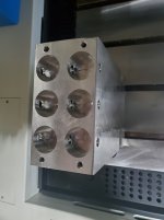
So a plate with ER collet holders if your trode blanks are round is nice because it's so convenient to change out and it's forgiving if the raw graphite stock is not consistent in diameter (it's often not!).

You are going to rely on the precision of the Kitamura to make all of the trodes spaced the proper known distance apart, and you will rely on the Kitamura to make each trode the proper shape.
But you don't KNOW that it can do that, after it warms up and the cutters wear and etc etc.

Traditionally, the way around that is to edge touch each electrode to each workpiece blank and establish their correct relationship...Makino can write you a routine to do that automatically, but there are things you must do too.

Principal of these is to space the parts and the trodes far enough apart that you can actually do the edge touches without crashing one of the other trodes into one of the other workpieces or making a touch on the wrong trode that you thought was on the correct trode.
The obvious way is to make the pitch of the trodes a twitch bigger than the pitch of the workpieces so you know you're touching the right trode to the right workpiece.

This is a fundamental constraint whenever you try to burn a gang trode into a gang workpiece setup and must have better precision than the crude setup shown in my last post.

Now it IS possible to try to make the workpiece setup and the milling of the gang trodes so damn accurate that you can just assume they are all in proper position and the trodes are all identical, but when it's tenths you care about, that's almost impossible to achieve.

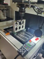
Since you have a toolchanger, you can make individual trodes in individual holders and circumvent all that bullshit: basically losing nothing but the toolchange time and the edge touch time which is truly trivial compared to the burn time.

So long as your workpiece spacing is far enough apart to allow trode to workpiece edge touches you will be able to position your trodes to the best precision the machine is capable of, even when you have a gang workpiece setup and you don't know exactly where each workpiece is sitting in the fixture.

The details of how to wash down the workpieces prior to those touches, how to ignore a false touch, how to calculate the origin from those touches, I leave to your Makino Application guys.
They've probably solved this set of problems a bazillion times already, and will be able to advise you better than I can.

Now understand that this is only for the FINISH burns...I still recommend a gang trode for the roughing burn...it will go faster and you don't need exquisite precision to knock out most of the meat before you semifinish and finish burn.

Moving on to workpiece clamping...if you commit to the edge touching for all finish burns you also don't care that much that the workpiece clamping be dead nuts accurate in terms of spacing.

It still needs to be decent if you gang rough, but it doesn't need to be dead nuts.
That frees you to concentrate on the other things it does need to be.
You need to clamp each workpiece dead nuts square and oriented properly to any other features the part may have that were put in prior to the burns.
That's just basic fixture design and I leave that to you.

But the other thing you need to care about is that pesky cleaning I talked about.
You will NEVER be able to clean it perfectly for all stations if it remains in the machine between part changes.
But the 3R clamping system is designed to be easy to clean in the machine...the crossed vees that locate the clamping plate to the receiver are super accessible and easy to inspect and there are only 8 exposed surfaces you must get right.
So take advantage of that.

Also take your cues for your fixture design from the 3R design...leave ample space where the shit can accumulate without getting onto your locating features.
Make the locating features accessible and easy to wipe down and inspect.
Make them hard and abrasion resistant...440C Stainless at 60+ RC if you want them corrosion resistant too, D-2 at 60+ RC if you don't need the corrosion resistance.
If you want to get fancy you could also have them nitrided or hard chromed.

Plan to buy yourself an ultrasonic cleaner big enough to hold a complete part fixture and make two so one can be burbling in the ultrasonic while the other is burning.

If you are willing to do all these things, I predict spectacular success.
I will remain super envious of your cool new toy.
Please don't forget to post pictures when it's successful and running.

Cheers

Marcus
www.implant-mechanix.com
www.vancouverwireedm.com
 
Last edited:
Marcus,

Wow, you are a wealth of info- you've been doing this for many years I imagine.

I see, yes I was trading off easy access trode replacement for hopefully precision, and your right I have no idea how fast they'll get used up or how precisely I can cut them-graphite and CuW is another new process. From your post it sound like very often.

ER collet sound like a much better idea! And so does using the 3R pallets. We have a large enough ultrasonic in house and it will be a lot easier and faster to clean collets, chucks and pallets then that fixture I cut.

Edge touches are definitely the least time consuming part of this. I'm going back to the drawing board...collets, pallets, hard metal, quick change trodes, fast cleanup.

Makino got her up and breathing today, spindle axis installed, fluid in, rough level done-POWER ON! Hopefully we'll be test burning on Wednesday.

Question: if you were going to burn a nice tight hole for a dowel pin, say .25" pin in a .2495" hole, what size would you cut your trode OD? Poco3 into tool steel S7@59Rc. .250" depth.

Thank you Marcus for you time and sharing!!

Rob
 
Hi Rob:
The whole idea of orbiting an electrode is to achieve three goals:

First is the ability to control your part size by simply changing the orbit and re-running the program.
The main gain that comes from this is that you don't have to care that much how big your trode actually is...just compensate for it by noodling with your orbit.

Second, you can distribute the wear more evenly over the surface of the trode.
Corner wear is your biggest source of geometric fidelity problems, so the most common mitigating tactic is to pre-drill your hole as big as you can get away with and make your trode small enough that you can drop it in the hole without it touching the sidewalls.
Now orbit it out, and what will happen is that you will start to burn along the whole length of the sidewall instead of at the bottom corners of the trode.
This preserves the trode and keeps the sidewalls of your hole as parallel as the electrode is parallel.
Just pretend your interpolating a hole on the milling machine...the process is almost identical.

Third is to improve the ability of the dielectric oil to flush the gap.
A typical gap for a fine burn might be 0.0005" or less.
Burning makes a continual stream of debris and you need to get rid of it continuously because you need to maintain the spark gap very precisely, and the cut debris is conductive which will short the trode to the workpiece and stall the burn.
If you make the trode significantly smaller and orbit it, the spark gap is maintained only in one very narrow zone at any one time, and the location of that zone is continually changing, allowing access everywhere else for the crap to come out.

A very common convenience is to allow 0.005" per side, so your trode for a 0.250" burn will be 0.240" diameter (convenient because it's easy to calculate).
But you don't have to care if it's 0.242" or 0.238"...just compensate with the orbit.
What you do have to care about is that it be truly cylindrical and oriented coaxially with your intended hole when you start your burn.
Of course it won't stay that way as soon as you begin your orbit, but your finished hole will end up in the correct spot once the orbiting path is complete.

You can also spin the trode as well as orbit it.
This improves the accuracy of the burn because it distributes the wear all over the surface of the trode and means that no wear pattern or surface defect on the trode can imprint itself into the sidewall of the burn.
If you got your machine with the C axis option, you can do this.

When you do this your trode must be spinning with as little runout as you can manage.
There are two ways to get there:
One is to adjust the position of the trode until the runout is essentially zero.
The second is to discharge dress or turn the trode while it is spinning in the machine.

There are three ways to do that too:
1) Make and mount a discharge dressing block somewhere in the worktank that you can position next to the trode, spin the C axis and then treat the trode as if it were a workpiece...burning bits of it away until it's running as concentrically as the C axis spindle will permit.

2) Mount a lathe tool in the worktank, treat the electrode blank as if it were the workpiece and just turn it with the C axis to spin it and the Z axis to traverse the trode past the cutter (works good for graphite...not recommended for copper).

3) Get the super fancy wire EDM attachment from Makino and "spin and burn" the trode.
This is super useful if you intend to make long skinny holes to exquisite levels of precision...I mean things like 0.004" holes 0.01" long to a tenth.

So the seemingly simple subject of burning a hole has quite a bit more to it than you may have considered...welcome to the wonderful EDM world.

Last, I thank you for your kind comments but my knowledge on this subject is actually pretty patchy.
The best resources for information I've ever discovered in decades of doing this comes from two places:

One is the application engineers (from Makino in your case), and Brian Pfluger is a particularly good one from all I've seen.
The second is a gentleman named Bud Guitrau, author of the EDM Handbook and a mountain of really good articles in some of the EDM magazines.
Pick the brains of these two guys...both are super generous with their knowledge, and their knowledge is vast and comprehensive.

Cheers

Marcus
www.implant-mechanix.com
www.vancouverwireedm.com
 
Last edited:
Wow, you have my brain working overtime again. Thank you Marcus. This really is a whole new world, its a different way of thinking vs milling or turning. I just bought Bud's book and Makino has been great, we'll have applications here in a week or so.
Here's our 1st controlled movements, they ran the machine in a cycle to max travel in all axis @ rapid for about 30 minutes to test for issues.
I was happy to see the attention to detail, (picture) using a ceramic square to check about 30+ different static measurements. Its quite a process and we haven't even gotten to dynamic or test burns-that's tomorrow.
Our installer is extremely knowledgeable and he's taking time to answer all my questions and teach me about my machine and good practice.

Thanks
Rob
 

Attachments

  • Qc-check.jpg
    Qc-check.jpg
    178.8 KB · Views: 19


Back
Top