What's new
What's new

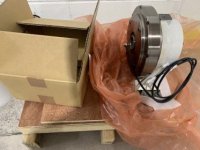
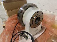
New Machine(s) Day! Brother S700X2 and Hardinge GT-27SP

“So what new in the X2 models over the X1's?”

X2’s have load monitoring. It’s not a slick as a Haas and takes some special M-codes to make it work and would take some macros to grab the next redundant tool but it’s there. We updated the firmware on the X1 and it’s missing the hardware for this.
 
I have yet to find one that is even close to being right, so I roll my own. But I am awfully picky about this stuff. I like to hold my fixtures between the 4th and a pneumatic tailstock so I can swap fixtures with 15 to 20 seconds of spindle down time so "getting it right" is a big deal for me.

Pics would be awesome!
 
I can look back at other quotes that I got but Brother offers an "end support" I think it is called? There are hydraulic, pneumatic, or hand-operated units but I had no plans to use any. If I had table-spanning thinner fixtures planned I would have. I had no issues with fixture sag using Lang 96mm plates on the Yukiwa or Nikken 4ths at the old shop including an old Kurt rota-vise that was easily 16"+ long. We had those bolted to sub plates that were connected to the table so we had clearance for some larger parts but they didn't overhang.

Congratulations on the new machine.

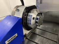
I bought the same machine recently. I got brother's support table with built in clamps. I haven't used it so far.

IMG_3907.jpg
IMG_3908.jpg


I made some adapter plates for 52 Quick Point vises.

IMG_3909.jpg

I found the dimensions are not as intended but they hold the vise within +- 0.04ish mm from actual position. Part of the reason is that I was not (and still not) measuring cutter diameter. I used values right from the label e.g. 6mm, 10mm etc. I am considering buying V anvil micrometer or radius measuring tool setter. And another thing I found was Z height also varies depending on if spindle is warmed up or not and it is not a small deviation (might be close to 0.1mm or so). I recently activated TDC and need to look into how to use it properly.

Anyways, as the centre of the vise is slightly misaligned with the centre of rotation in both Z and Y, Rotary Fixture Offsets would have be ideal solution. Since the centre of rotation is known (170mm in Z and -200mm in Y) and X is pretty easy to measure, I can set them to G54, etc and then set G54.2 P?? on the part. I should take care of the misalignment and tract the WCS with the rotation of 4th.


But I have no idea how to work with them in Fusion 360. Spent some time on forums and found no solution. Finally I thought let's just try outputting program. I used proper "Tool Orientation" for each tool paths and went ahead with Post Processing. Selected "Use A" in the NCCode window, it outputs program without any error. There is nothing in the program to rotate 4th.

Then I tried changing var useMultiAxisFeatures = true (default is false);

This outputs the code with G68.2 (Feature Coordinate System) and then G53.1 (Feature Coordinate Index). I spent close to a week reading about G54.2 and G68.2 and how to get fusion 360 to output them only to find out that I don't have these options installed on the machine. They are paid options.

Only option at this point is to have Workpiece Zero Points for all rotations which is very time consuming. I think it will be better to do 3 axis setup in 2 operations rather than machining all sides and then touching up for WCS in all orientations.

Even if I go ahead doing that, still no idea how to get rotations from Fusion 360 post without splitting into multiple setups (in Fusion 360) and post them out separately and then manually add G0 A?? and call appropriate programs.


I am curious how are you going to program for the 4th axis especially in Fusion (If I am not mistaken you are using Fusion 360?).
 
Congratulations on the new machine.

I bought the same machine recently. I got brother's support table with built in clamps. I haven't used it so far.

View attachment 334519
View attachment 334520


I made some adapter plates for 52 Quick Point vises.

View attachment 334521

I found the dimensions are not as intended but they hold the vise within +- 0.04ish mm from actual position. Part of the reason is that I was not (and still not) measuring cutter diameter. I used values right from the label e.g. 6mm, 10mm etc. I am considering buying V anvil micrometer or radius measuring tool setter. And another thing I found was Z height also varies depending on if spindle is warmed up or not and it is not a small deviation (might be close to 0.1mm or so). I recently activated TDC and need to look into how to use it properly.

Anyways, as the centre of the vise is slightly misaligned with the centre of rotation in both Z and Y, Rotary Fixture Offsets would have be ideal solution. Since the centre of rotation is known (170mm in Z and -200mm in Y) and X is pretty easy to measure, I can set them to G54, etc and then set G54.2 P?? on the part. I should take care of the misalignment and tract the WCS with the rotation of 4th.


But I have no idea how to work with them in Fusion 360. Spent some time on forums and found no solution. Finally I thought let's just try outputting program. I used proper "Tool Orientation" for each tool paths and went ahead with Post Processing. Selected "Use A" in the NCCode window, it outputs program without any error. There is nothing in the program to rotate 4th.

Then I tried changing var useMultiAxisFeatures = true (default is false);

This outputs the code with G68.2 (Feature Coordinate System) and then G53.1 (Feature Coordinate Index). I spent close to a week reading about G54.2 and G68.2 and how to get fusion 360 to output them only to find out that I don't have these options installed on the machine. They are paid options.

Only option at this point is to have Workpiece Zero Points for all rotations which is very time consuming. I think it will be better to do 3 axis setup in 2 operations rather than machining all sides and then touching up for WCS in all orientations.

Even if I go ahead doing that, still no idea how to get rotations from Fusion 360 post without splitting into multiple setups (in Fusion 360) and post them out separately and then manually add G0 A?? and call appropriate programs.


I am curious how are you going to program for the 4th axis especially in Fusion (If I am not mistaken you are using Fusion 360?).

Sounds like Fusion isn't the problem, you need to make some more tweaks to your post. Did you change this?

useAAxis: {
title : "Use A-axis",
description: "Specifies whether to use the A axis.",
type : "boolean",
value : false,
scope : "post"
 
Sounds like Fusion isn't the problem, you need to make some more tweaks to your post. Did you change this?

useAAxis: {
title : "Use A-axis",
description: "Specifies whether to use the A axis.",
type : "boolean",
value : false,
scope : "post"

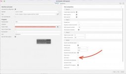
This is only a declaration of property "Use A-Axis" for scope of "Post Process environment" which makes it appear as a check box as follows in the dialogue.

Screen Shot 2021-11-15 at 2.55.24 PM.jpg
 
Get your post figured out, that is the issue. Machining multiple faces with your 4th is a game changer as far as productivity goes. I have a good Fusion post with 4th axis for a Yasnac control if you want one to compare to.
 
The apps guy told me the G54.2 and G68.2 don't work very well? I know at the old shop we just stuck WCS geometry into each side of the fixtures but that was before they had the option. We had to do the same thing on the M140s.

I have not tried posting 4th axis code, but I have posted with the A axis turned on in the post and it does call the A0. I was going to try something later this week so I will for sure update.
 
Even if I go ahead doing that, still no idea how to get rotations from Fusion 360 post without splitting into multiple setups (in Fusion 360) and post them out separately and then manually add G0 A?? and call appropriate programs.

I just did this on a cubic part.

Create a setup, tell it to use the Speedio machine definition (with the axes set correctly and an A axis on X). Add two ops, one on each face of the cube. In "geometry" for the ops, set tool orientation so Z is properly oriented. Post the entire setup, be sure to check "use A axis" in the "general" section.

Code:
(2D ADAPTIVE4)
N20 G54
N25 G100 T01 X-21.122 Y-2.828 G43 Z40 [B]A90.[/B] H01 D01 S15915 M03
...
(2D ADAPTIVE4 2)
N16795 G00 [B]A0.[/B] X-35.355 Y-2.828
...

Hope that helps!
 
Reading over this thread a few times is making question if my original choice in a doosan is the correct one. I'm truly having a hard time getting a speedio vs a doosan. Parts I make are mostly alum/brass little bit of steel. 2.5" tall alum is the biggest part. Steel is under 2" Looking at 16k big plus S1000 (now call the W1000).
 
Reading over this thread a few times is making question if my original choice in a doosan is the correct one. I'm truly having a hard time getting a speedio vs a doosan. Parts I make are mostly alum/brass little bit of steel. 2.5" tall alum is the biggest part. Steel is under 2" Looking at 16k big plus S1000 (now call the W1000).

A member here from the bay area machined these on his Speedio and was very happy with the results. Knocked the cycle time to about a third of his 40 taper he replaced. He finished the inside at full depth. It was around 3" deep as I recall.

010.jpg

013.jpg

012.jpg
 
Funny enough I'm finding I've been absolutely spoiled by the OSP control. It isn't just because I run it more since I've got plenty of Fanuc and Brother experience (plus two Fanucs in the shop on my turning centers), but it is just a really well thought out interface with a ton of features.

I should also mention that I never knew about the C00's restart ability. I don't recall if it was on the earlier versions at the old shop, but the apps guy showed me how to use it and the mechanics are similar to how the OSP does a restart/recovery.

Every time I post code I notice more things I'd like to change. I still don't understand Fusion/HSM's logic on the M298 calls.

No time today to play around - I've got a stack of torque plates to go out the door (I've been waiting on DOM tubing of all things).

Your fusion post puts out 298 codes? How did you get it to do that?
 
Your fusion post puts out 298 codes? How did you get it to do that?

The new post processor does this. While playing around the the post I have it set to any stock to leave more than 0.015 to run L2, L3 is for 0.014- 0.002, finish L5 is stock to leave at 0.
 
Your fusion post puts out 298 codes? How did you get it to do that?

It is in the stock post - I just turned on the simplified smoothing function.

ETA: It would be nice to be able to have it output L0 for roughing strategies. I'll figure it out eventually but for no I'm hand editing.
 
Your fusion post puts out 298 codes? How did you get it to do that?

You need the current post. When you go to post the setup, you'll see "Group 2" options. Change "High accuracy mode" to "M298" and "High accuracy level" to "Automatic."

If you use stock to leave over or equal to 0.5 mm, it'll rough (M298 L2 by default); 0.1 to 0.5 mm, semi-rough (L3); 0.1 to 0.05 semi-finish (L4), below that finishing (L5). It's pretty slick.
 
ETA: It would be nice to be able to have it output L0 for roughing strategies. I'll figure it out eventually but for no I'm hand editing.

In the stock post, it's line 553. Just change this:

Code:
  roughing              : 2, // roughing level for smoothing in automatic mode

to

Code:
  roughing              : 0, // roughing level for smoothing in automatic mode
 
The new post processor does this. While playing around the the post I have it set to any stock to leave more than 0.015 to run L2, L3 is for 0.014- 0.002, finish L5 is stock to leave at 0.

I'm not literate in posts or modifying them, while I have played with the fusion posts a little when I first got my brother. How did you change the values? I typically rough down to .003-.005.

I'm too incompetent in programming languages that I have searched 3 or 4 times for the G53 it outputs to try and stop it from posting an x0 y0 and can't even fix that :nutter:

I'm glad you guys are here, I would never figure this stuff out on my own.

The thresholds start at line 667 (search for thresholdRoughing). There is no thresholdMediumRoughing because that falls between roughing and semi-finishing, it uses the semi value for L.

If you want to stop it from posting out the zero return at the bottom, I think that is in the writeRetract()) function. The home positions are set starting at line 3085; after it checks for G28) there are some ternary statements to set the home position by axis. These look like a = thing ? value 1 : value 2) and you can read them as "if thing is true, use value 1; else, use value 2." You could comment these out and replace them with specific values, like this:

Code:
//    _xHome = machineConfiguration.hasHomePositionX() ? machineConfiguration.getHomePositionX() : toPreciseUnit(0, MM);
    _xHome = toPreciseUnit(-250, MM);

I am not sure if this is completely safe, but it seemed to do the right thing when I tested it just now :popcorn:
 
Thanks for that! I haven't dug into the logic yet - been too busy. I still need to make some changes to the Okuma post and develop one for the new Hardinge. I'm sure the Hardinge will be pretty simple.


Back
Top