How to install the app on iOS
Follow along with the video below to see how to install our site as a web app on your home screen.
Note: This feature may not be available in some browsers.
You are using an out of date browser. It may not display this or other websites correctly.
You should upgrade or use an alternative browser.
You should upgrade or use an alternative browser.
Old Autocollimator Parts
- Thread starter Mk1_Oz
- Start date
- Replies 35
- Views 2,017
ballen
Diamond
- Joined
- Sep 25, 2011
- Location
- Garbsen, Germany
I am also looking for two parts:
(1) the objective lens for a Hilger Watts TA4 autocollimator. This is the glass lens at the very front of the device, and is approximately 37mm in diameter and 8mm thick at the edge. The drawings indicate that it is plano-convex, meaning flat on one side and convex on the other side. This might be the same lens used in TA1 TA2 TA3 and TA5 models.
(2) the small half-silvered mirror which reflects the lamp light and sends it onwards through the crosshairs and objective lens to the target.
If anyone has these for sale, please drop me a note. Alternatively, I may get one custom made. I think the focal length is just the distance from the lens center to the plane of the crosshairs, because there are no intervening optics. I am told that there are CNC lathes that turn plastic lenses for eyeglasses in seconds, with optical quality surfaces and precision. So perhaps there is a company out that that can turn lenses "to order".
Last edited:
ballen
Diamond
- Joined
- Sep 25, 2011
- Location
- Garbsen, Germany
A couple of comments for the records. I made some further measurements: the correct lens OD is 36.95mm and the correct back focal length is 270mm (lens mount to crosshairs). This was originally a cemented doublet (achromic) lens, made from a crown glass biconvex part and a flint glass planoconcave part.
EDIT: I just confirmed this with the June 1960 manual on page 3, which has: "in the Microptic Auto-Collimator the focal length of the objective f is 10.8in." That's 274.32mm. Since the lens has a thickness of about 8 or 9mm, my back focal length value of 270mm is almost exactly correct.
EDIT: I just confirmed this with the June 1960 manual on page 3, which has: "in the Microptic Auto-Collimator the focal length of the objective f is 10.8in." That's 274.32mm. Since the lens has a thickness of about 8 or 9mm, my back focal length value of 270mm is almost exactly correct.
Last edited:
John Garner
Titanium
- Joined
- Sep 1, 2004
- Location
- south SF Bay area, California
Edmund Optical (or is it Optics?) has supplied close-enough-to-work lenses, mirrors, and beamsplitters a good number of times that I knew of.
I've also successfully replaced beamsplitter cubes with pellicles a few times. Had to improvise a metal-or-plastic 45-90-45 degree diagonal half cube to hold the pellicle. (Quick tip: make the cube, drill intersecting holes through 2 centerlines, and mill away the half cube you don't want.)
I've also successfully replaced beamsplitter cubes with pellicles a few times. Had to improvise a metal-or-plastic 45-90-45 degree diagonal half cube to hold the pellicle. (Quick tip: make the cube, drill intersecting holes through 2 centerlines, and mill away the half cube you don't want.)
ballen
Diamond
- Joined
- Sep 25, 2011
- Location
- Garbsen, Germany
Hi John, thank you, I was hoping you would weigh in. You have lots of real-world experience, and I am a rank beginner with none of that.
Edmund doesn't have suitable lenses in diameters > 25.4mm. Also, in that diameter, they only have focal lengths of 250 and 300mm, not 275mm.
Ross Optical has a lens that looks quite close, part number L-AOC222. This has a diameter of 38.1mm (about 1.1mm too large) and a focal length of 280mm (5.7mm too long). The 1.1mm larger diameter can be accommodated with a modified lens carrier, and the extra 5.5mm of focal length is within the range of the focusing mechanism. So I may go this route.
John, could you tell me your opinion regarding the beamsplitter quality? Can I use a "normal" off-the-shelf 50/50 silvered mirror? Or do I need to get a beamsplitter that is flat to 2 x lambda or lambda/4 or parallel to that amount?
In the instrument, the beamsplitter holder consists of a machined (not ground) brass 45-degree surface, with two bronze-copper spring clips to hold the beamsplitter against that. It looks as if the beamsplitter is 1-2mm thick. So not a holder that would maintain a surface to lambda/4 from what I can see.
Cheers,
Bruce
PS: if you don't understand my question about beamsplitters, I can give links to some different models and their specs. There is a range of flatness available from unspecified to 6 x lambda to lambda/10. These are typically "per inch". It is not clear to me how flatness errors in the beam splitter propagate to angle errors in measurements.
[EDIT] I talked this through with a couple of colleagues who know more about optics than I do. The conclusion is that even a "bad" (meaning: not flat) beamsplitter is OK. Here is the argument:
The purpose of the beamsplitter is to illuminate the crosshairs. But the crosshairs are sitting exactly in the focal plane of the objective. So any light rays that leave the crosshairs and enter the objective will be correctly collimated at infinity. It does not matter how those light rays reached the crosshairs, or in what direction. The only potential effect of a "bad" beamsplitter is that it will waste some light that will go in the wrong direction and not make it to the objective. But this is not enough light to affect the function, and having the "wrong angle" on the illumination rays does not matter, since the crosshairs sit in the focal plane.
Last edited:
daryl bane
Titanium
- Joined
- Mar 12, 2002
- Location
- East Texas
Would it be possible to grind down the new larger objective to fit? I wonder if an eyeglass optical shop could do that?
ballen
Diamond
- Joined
- Sep 25, 2011
- Location
- Garbsen, Germany
Hi Daryl, yes, that's possible. But there is some danger that they will get the optical center wrong. A typical optical element is centered to within a few microns, whereas an eyeglass shop typically look at your eye and marks a spot which appears to be at the center of your pupil. They probably get it right to 1 mm, but are not used to getting it closer than that. Here I think I want to be better than 100 microns. So machining a new lens carrier seems a more reliable solution, and I can do that in a couple of hours in my own workshop. Cheers, Bruce
Last edited:
daryl bane
Titanium
- Joined
- Mar 12, 2002
- Location
- East Texas
Of course, you could just run down to Oberkochen, and let Zeiss make up you a replacement. I'm sure they would be glad to help.  .
.
 .
.ballen
Diamond
- Joined
- Sep 25, 2011
- Location
- Garbsen, Germany
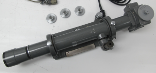
Here is what a TA4 autocollimator looks like (for the record, this is not mine).
I have a question which the owner of one of these autocollimators can easily answer. Shown below is the assembly which hold the objective lens. On the left is a blued steel cap, visible from the outside the instrument. The next three parts are a brass threaded shell that holds the lens, then a brass serrated baffle which prevents glancing reflection at the edge, and finally the brass threaded cap that mates to the threaded shell. The lens goes inside this three-piece brass shell, which is then held inside the instrument by the steel cap.
My question: does the baffle (third item from left) go on the outside side of the objective lens, or does it go on the inside side of the objective lens? I am guessing the latter, but am not sure. If someone who owns one of these looks at it, and the serrated baffle is not visible on the outside, that would confirm my guess.

Here is the periscope assembly which brings light into the body of the autocollimator. On the top is a focusing lens, which takes in diffuse lamp light
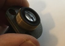
and on the bottom is the (currently missing) beam splitter, which is a 45-degree elliptical partly-silvered mirror, dimensions approximately 18 x 25 x 1 mm.
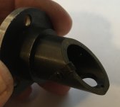
One of the two retaining clips is missing.
This fairly crude holder indicates to me that the beam splitter is not a precision optical flat component.
Cheers,
Bruce

I have a question which the owner of one of these autocollimators can easily answer. Shown below is the assembly which hold the objective lens. On the left is a blued steel cap, visible from the outside the instrument. The next three parts are a brass threaded shell that holds the lens, then a brass serrated baffle which prevents glancing reflection at the edge, and finally the brass threaded cap that mates to the threaded shell. The lens goes inside this three-piece brass shell, which is then held inside the instrument by the steel cap.
My question: does the baffle (third item from left) go on the outside side of the objective lens, or does it go on the inside side of the objective lens? I am guessing the latter, but am not sure. If someone who owns one of these looks at it, and the serrated baffle is not visible on the outside, that would confirm my guess.

Here is the periscope assembly which brings light into the body of the autocollimator. On the top is a focusing lens, which takes in diffuse lamp light

and on the bottom is the (currently missing) beam splitter, which is a 45-degree elliptical partly-silvered mirror, dimensions approximately 18 x 25 x 1 mm.

One of the two retaining clips is missing.
This fairly crude holder indicates to me that the beam splitter is not a precision optical flat component.
Cheers,
Bruce
Last edited:
ballen
Diamond
- Joined
- Sep 25, 2011
- Location
- Garbsen, Germany
I would guess that getting Zeiss to make a custom lens is at least four figures. I'm strictly looking at off the shelf.Of course, you could just run down to Oberkochen, and let Zeiss make up you a replacement. I'm sure they would be glad to help..
johansen
Stainless
- Joined
- Aug 16, 2014
- Location
- silverdale wa
I have yet to fix my davidson d638 but i did find out for relative certainty that the reticle does not need to be at the focal point of the objective lens.Hi John, thank you, I was hoping you would weigh in. You have lots of real-world experience, and I am a rank beginner with none of that.
Edmund doesn't have suitable lenses in diameters > 25.4mm. Also, in that diameter, they only have focal lengths of 250 and 300mm, not 275mm.
Ross Optical has a lens that looks quite close, part number L-AOC222. This has a diameter of 38.1mm (about 1.1mm too large) and a focal length of 280mm (5.7mm too long). The 1.1mm larger diameter can be accommodated with a modified lens carrier, and the extra 5.5mm of focal length is within the range of the focusing mechanism. So I may go this route.
John, could you tell me your opinion regarding the beamsplitter quality? Can I use a "normal" off-the-shelf 50/50 silvered mirror? Or do I need to get a beamsplitter that is flat to 2 x lambda or lambda/4 or parallel to that amount?
In the instrument, the beamsplitter holder consists of a machined (not ground) brass 45-degree surface, with two bronze-copper spring clips to hold the beamsplitter against that. It looks as if the beamsplitter is 1-2mm thick. So not a holder that would maintain a surface to lambda/4 from what I can see.
Cheers,
Bruce
PS: if you don't understand my question about beamsplitters, I can give links to some different models and their specs. There is a range of flatness available from unspecified to 6 x lambda to lambda/10. These are typically "per inch". It is not clear to me how flatness errors in the beam splitter propagate to angle errors in measurements.
[EDIT] I talked this through with a couple of colleagues who know more about optics than I do. The conclusion is that even a "bad" (meaning: not flat) beamsplitter is OK. Here is the argument:
The purpose of the beamsplitter is to illuminate the crosshairs. But the crosshairs are sitting exactly in the focal plane of the objective. So any light rays that leave the crosshairs and enter the objective will be correctly collimated at infinity. It does not matter how those light rays reached the crosshairs, or in what direction. The only potential effect of a "bad" beamsplitter is that it will waste some light that will go in the wrong direction and not make it to the objective. But this is not enough light to affect the function, and having the "wrong angle" on the illumination rays does not matter, since the crosshairs sit in the focal plane.
So i have my davidson mostly working. The flat plate beam splitter is located approximately where the original cube beam splitter was.
The reticle (a wire) is located between the objective lens and the splitter. The return image of the wire is in focus on the movable glass plate, which is observed through an eyepiece.
The original design has the reticle between the cube beam splitter and the light source, and it is a darkfield reticle. A plate of glass with the chrome etched away in a series of concentric rings.
An additional concave lens (which i dont have) is placed between the cube beam splitter and the magnifying lenses to help focus the returned image of the reticle onto the glas plate. I cant put the reticle where it was originally without that exact lens, because it would be out of focus, optically it is further away from the moveable glass plate
Additionally, the micrometer dial would be meaningless without callibration.
When i point the autocollimator at the sun, iirc the focus point is 3 to 5 inches past the light source.
Last edited:
daryl bane
Titanium
- Joined
- Mar 12, 2002
- Location
- East Texas
Ha, I couldn't imagine what Zeiss would charge for a single one off, if they would even do it, now maybe for 1000 pcs. they might talk to you. Actually, I don't know if this is correct, but I think...think that most of their production glass (and just about everybody else's) is now made in China.I would guess that getting Zeiss to make a custom lens is at least four figures. I'm strictly looking at off the shelf.
John Garner
Titanium
- Joined
- Sep 1, 2004
- Location
- south SF Bay area, California
I've been trying to remember what instruments I've improvised beamsplitters for, and the ones I've been able to recall have all been "bright-field" autocollimators . . . which means that the beamsplitter needs to deflect light in one direction and pass an image of both the real and image reticle going the other way.
Any defocus created by such a beamsplitter influences both the outgoing and returned beams in the same ways. This makes me think that the planarity error of the beamsplitter surfaces is not critical.
If the beamsplitter deflects a reticle image, the beamsplitter planarity may be more important. To the best of my knowledge, "bright line" autocollimators universally use the beamsplitter to deflect a reticle-pattern of light into the objective lens system.
In either case, and again to the best of my knowedge, the real reticle and the image reticle must both be very nearly in the same plane, and very near the objective lens system focus to avoid parallax.
Do note that the objective lens SYSTEM may include focusing lenses, which means that the objective focus and the objective system focus are separated. In fact, the focusing lens may not be a single lens, but a second system of lenses.
Furthermore, the focusing lens system may be positive (convex) or negative (concave). Beyond the fact that a positive focusing system effectively makes the effective focal length of the objective lens system shorter than the focal length of the objective lens proper -- and vice-versa -- I don't remember how the positive-or-negative focusing lens system choice influences other properties of the objective lens system.
jccaclimber
Stainless
- Joined
- Nov 22, 2015
- Location
- San Francisco
If you wanted a 1 off lens and could tolerate it being an optical plastic you would get it diamond turned instead of glass. Would still not be cheap, nor scratch resistant.
ballen
Diamond
- Joined
- Sep 25, 2011
- Location
- Garbsen, Germany
John: the TA4 that I am working on is bright field, dark crosshairs. As you say, the beamsplitter accepts light coming vertically from the lamp/lens and deflects it 90 degrees. That light then passes the crosshairs, and continues to the objective. Light reflected from the target mirror then returns in the opposite direction, passes through the objective, then passes through the beamsplitter and into the eyepiece. It seems clear from the engineering of the mount that this is not intended to be an optically flat surface.
Jccaclimber: indeed, I am looking for less expensive solutions.
All: I just purchased a cemented doublet, 51.5mm diameter, 270mm focal length for about $20. When it comes, I am going to reduce the diameter. My three options are:
- take it to a local optician, who grinds in down in lens-edging machine
- mount it on my cylindrical grinder and use a diamond wheel to grind it down
- mount it on my mill in an aluminium holder, and use a 38mm diamond hole saw to drill out a 37mm diameter plug.
All three options involve flood coolant.
Last edited:
Peter.
Titanium
- Joined
- Mar 28, 2007
- Location
- England UK
Wherever did you find such a doublet Bruce? A new part, NOS or just happened upon a used one? I should think that you must have been very lucky!
ballen
Diamond
- Joined
- Sep 25, 2011
- Location
- Garbsen, Germany
The lens is from Alibaba express:
Note that the FL of 270mm is 4.5mm shorter than the stock part, and that the diameter of 51.5mm is about 15mm larger than the correct diameter (just under 37mm). I will try to grind it down, but if that fails, I'm prepared to chalk it up to experience. The other option is a lens from Ross Optical. This is model L-AOC222, has a FL of 280mm (5.5mm too long) and a diameter of 38.1mm. With some modification it might be possible to fit that into the autocollimator, but ideally it would also be ground down.
I've also ordered some 1.1mm thick half-silvered beam splitter material, and will try and shape that into an ellipse of the correct dimensions (18 x 25mm).
jccaclimber
Stainless
- Joined
- Nov 22, 2015
- Location
- San Francisco
IME fine diamond wheels on surface grinders leave much nicer edges than plated hole saws on mills, though I’ve only used really cheap hole saws.
I guess the optician option depends on what they charge.
I guess the optician option depends on what they charge.
ballen
Diamond
- Joined
- Sep 25, 2011
- Location
- Garbsen, Germany
That's why I'm going to diamond wheel it on my cylindrical grinder, if the local opticians shop won't take it on.IME fine diamond wheels on surface grinders leave much nicer edges than plated hole saws on mills, though I’ve only used really cheap hole saws.
I guess the optician option depends on what they charge.
ballen
Diamond
- Joined
- Sep 25, 2011
- Location
- Garbsen, Germany
A couple of days ago, the 50/50 beam splitter arrived from China. It's 1.1mm thickness, 25.4mm diameter (round), last item on the pull-down list here. To mount it, I needed to shape it into an ellipse. I wasn't confident that I could scribe and break it, so instead I ground it to shape. The grinder is a cheap diamond disk (500 grit) mounted on my lathe, in a water bath (from a Tormek grinder). I was able to spin it at 180rpm without spraying water, though much faster would have worked more quickly.
I was worried that grinding would be stressful and was prepared to do this with protective goggles and a respirator and perhaps some protective gloves. In fact the grinding was very calm, the water prevented any dust, holding the glass in my fingertips gave excellent control, and I never felt that there was any damage of the beamsplitter shattering or breaking. The piece of wood on the compound was mean to be a hand-rest, but the technique that I quickly adopted was to stand and stroke the glass across the diamond wheel with a rotating motion. Maintaining a small contact patch worked best, just like with single-point tooling, so I avoided grinding flats.

I covered the beam splitter with blue painters tape and cut out the correct ellipse shape with a sharp knife, then ground it on the diamond disk.
The photo below shows it half-ground and half-round.

This worked very well. Here is the fit
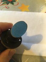
It took some time to make the mounting clips. I had one model and one screw, but decided to make the other two from copper because I didn't have suitable brass sheet stock on hand.

After the fitting, I painted the copper and screws black with a Sharpie, then remove the tape and mounted it. Note that the coated reflective surfaces faces the light source (up). Here's the final result before inserting back into the autocollimator.
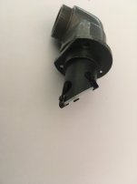
The double reflection on the photo below shows that the beam splitter is the correct way around: the half-reflective surface is on the inside of the periscope.


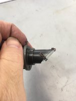
Note that my larger clips to not obscure the light path from the light source inside the periscope, or from the return image of the target that passes through the small hole.
I was worried that grinding would be stressful and was prepared to do this with protective goggles and a respirator and perhaps some protective gloves. In fact the grinding was very calm, the water prevented any dust, holding the glass in my fingertips gave excellent control, and I never felt that there was any damage of the beamsplitter shattering or breaking. The piece of wood on the compound was mean to be a hand-rest, but the technique that I quickly adopted was to stand and stroke the glass across the diamond wheel with a rotating motion. Maintaining a small contact patch worked best, just like with single-point tooling, so I avoided grinding flats.

I covered the beam splitter with blue painters tape and cut out the correct ellipse shape with a sharp knife, then ground it on the diamond disk.
The photo below shows it half-ground and half-round.

This worked very well. Here is the fit

It took some time to make the mounting clips. I had one model and one screw, but decided to make the other two from copper because I didn't have suitable brass sheet stock on hand.

After the fitting, I painted the copper and screws black with a Sharpie, then remove the tape and mounted it. Note that the coated reflective surfaces faces the light source (up). Here's the final result before inserting back into the autocollimator.

The double reflection on the photo below shows that the beam splitter is the correct way around: the half-reflective surface is on the inside of the periscope.


Note that my larger clips to not obscure the light path from the light source inside the periscope, or from the return image of the target that passes through the small hole.
Last edited:
Similar threads
- Replies
- 5
- Views
- 2K
- Replies
- 9
- Views
- 379

