What's new
What's new

Our new American pacemaker lathe - Ongoing cleanup.

The OD is exactly 24.00. I am wondering if my digital calipers are playing tricks on me when measuring bores. I measured the shaft the bearings sits on and I got 8.00mm and 8.01 with my micrometer and 8,00 with my Hazet vernier caliper. So I guess the ID of the bearing is actually 8.00mm.
Which makes the Fafnir bearing fit perfectly! I have sent an inquiry now, will let you know how it goes.
Thank you for the help John !
 
Digital calipers are useless for bearing fit work. You can get within a couple thousandths of an inch (.002), but bearing work is ten times more accurate (tenths... .0001). They will give you a general idea, but for precise internal measurement, go to telescope or bore gauges and vernier mics.
 
Tailstock assembly

I just fixed the issues I had with the tailstock:
1. Could not get the gears to engage again after moving the quill out of engagement towards the headstock.
2. The quill was very sticky and hard to move in the high-gear (this is a two-speed tailstock). So much so that I thought the gear-lever was a lock and not high-gear.

I got a tip by personal message to beat it out with a hammer, and it worked (thank you for the tip).

Here's how to do it. Slightly improved compared to how I did it to begin with.
  • Crank the quill all the way out of engagement.
  • Remove rear cover, and side cover on the back side of the TS.
  • Clamp tailstock firmly to the bed.
  • Get a piece of wood (about 2x3") the same length as the tailstock and put it inside the TS.
  • Makes sure the quill has somewhere safe to land.
  • Use a heavy piece of wood or something similar to thump against the wood inside the TS. Weight is the thing here. I tried with a small sledgehammer and it was slow going. With the heavy piece of wood it went fast.
  • Clean up any dirt/oil/grease and burrs on the quill and inside the TS and feed housing.
  • Oil the quill and insert into TS.
  • Get a piece of wood and jam it between the chuck and the tailstock quill. Oil TS liberally - I put some inside to start with and kept a good flow on top of the quill where it enters as it moved inward.
  • Use the feed of the TS to press the quill home. Make sure the key and the slot match up.
  • As you get close to the pinion: Start moving the quill feed to make it engage correctly.
  • Close up the covers and Bob's your uncle. Make sure the drain hole of the back cover is facing down and is not painted over.. :nutter:
Now the handwheel spins several turns in low gear by itself if I give it a good twirl. Second gear is now much lighter to move than 1st gear was before.

Mike C. - Thanks for the information. Will measure using the proper equipment in the future :)
 
Congratulations on your acquisition! We had one about that size at the first shop I worked at and it was one of my favorite machines I have ever run. I think the pacemakers are some of the most user-friendly manual lathes with their controls and gearboxs. We have a 31x280 at the shop I am at now and it is just purely a monster. It is very very sloppy in the cross-slide, making it difficult to get an accurate size, but it cuts with less than .005 diametral deviation over 200 inches once a cut has been dialed in. I would have liked to see that machine in its hayday 30 years ago. I'd also like to see my boss have that machine repaired and returned to its former glory!
 
Thanks J_Mac333 ! Wouldn't we all like to own a new-in-box Pacemaker ?

The tailstock taper has seen better days: Quite rusty inside and it's not a very nice surface as evenness goes either.
My plan was to use a Morse taper reamer and give it a slight reaming. I tried it just now but the reamer is bottoming out before the flutes start to cut. I can see where it has hit the edges at the bottom of the taper.
One solution is to grind the end of the reamer down a little, but I am slightly worried that the taper should be as deep as the reamer. Or are MT reamers always longer than the tools going into the taper ? Another solution would be to drill/turn out the bottom of the taper.

Filled both the tailstock gearbox and the tailstock way/quill lube up now. No leaks :)

PS: How much pressure does a MT4 hand reamer really need to cut properly ?
 
Last edited:
Panza ,
I don’t know about your machine but in some cases the MT. sockets in tailstocks or drilling machine spindles are made of alloy steel or are hardened to some degree either by heat treatment or by case hardening , perhaps not as hard as a reamer but that will affect the cutting pressure required and the the life of the reamer.
I have seen some sockets that were hard enough that forcing an H.S.S. reamer into them only resulted in the reamer needing to be sharpened and the socket had to be refinished by internal grinding .
You would get some indication of how hard it is if you try drilling the end of the socket a little deeper as you mentioned.
I think Morse taper Reamers are usually made to a standard measurement that used to be shown in the engineering tables in some tool cutting catalogues or places like Machinery’s Hand Book.
A reamer that has been re-sharpened will go deeper into the hole before cutting .

Regards,
Jim
 
Does this tailstock ram have a slot in the side at the end of the taper? If so, that's for the drive tang on MT tooling and may be what your reamer is hitting. Yes, the taper reamer has to be longer than MT tooling or the tooling might bottom before seating full in the taper. Either way, I think I'd let the lathe fix itself. Chuck the ram, zero it out and bore the bottom of the taper with a carbide boring bar, in case things are hardened. You can then try the reamer. I am 99.999% sure the ram on the big Pacemaker at the pump shop was not hardened, so it should clean up really quickly. If you have a brand new piece of MT tooling, you can blue that up and bump it in, then remove to see where the bad burrs are. I did that with the little Leblond at the pump shop and just clipped the burrs out with a fine half-round file. Worked well.
 
As Mike C. mentioned, sometimes better to leave well enough alone. Check for"highspots" by bluing a harden & ground dead center and file out by hand like Mike said. Whatever you do don't do what I did one time, use a air grinder with a carbide burr to remove burrs from the taper! I've tore up more reamers trying to smooth out the burrs, the reamer flutes would break down at every burr it would encounter!
A few of the tailstock rams I've seen were made of a tough alloy called "Finkl" steel. It will "work harden" from the nasty burrs created!
 
Thanks for the answers both Mike and Jim !
I cleaned up some burrs on the outside of the ram and I had no problems taking them down with a file, so boring it out should be no problem as far as hardness goes.
The ram does have a slot at the end of the taper, and it has been used (a lot), and it is indeed what the reamer is hitting.
It think I'll do as you suggest Mike, let the lathe fix itself. But before that is going to happen I must buy or make a steady rest, as I doubt that 2 feet ram is going to stay put in the chuck without help :eek:
Cleaned out the oil filter today too. Wasn't too bad, but about 1" of thick goo at the bottom. It's a really ingenious filter really. should have taken a picture. If anyone wants to see I'll take it out again. Also drained the oil from the gearbox and took of the top cover: Man there are some huge gears in there, and everything is built for war.
Note to self: Bring camera next time.
 
mt4 tailstock quill

Hi, Sorry for poking my nose in, but i just wondered if there is any provision for ejecting the tail stock centre. I have a Churchill lathe on which you just wind back the quill and a fixed stop inside ejects the centre. Here in the uk i dont get to see much American Iron but hold it in high esteem since my purchase of a K&T 3CE horizontal milling machine which has served me well with no real problems for the last five years. Must say my mouth waters looking at pictures of your lathe.
Steve
 
Panza ,
I was at first more concerned that you didn’t dull your reamer than with the way that you would actually ream it that Mike has described very well.
I guess with out reading that first, my thought would have been to make sure the tailstock barrel was adjusted concentric with the headstock spindle ie. not cutting taper with the adjustment on the tailstock base
Then place a drill or flat bottomed offset boring tool or reamer of the right diameter in the headstock chuck and with the lathe running, slowly advance the tailstock barrel into the tool and see what happens.
If you you were successful with that part you could place a true running center in the headstock to support the shank end of the taper hand reamer and advance the tailstock barrel by hand while you turned the reamer with a wrench or tap handle to clean out the bore.
using a little cutting oil or tapping fluid of some kind would help the reamer cut .
I was a little reluctant to suggest this since it might not be an “approved” or correct method but I can imagine that it has been tried somewhere before .
However it might allow you to get some use out of your lathe until you get a steady rest and have the time to do a proper job later.
I think just chucking the and running the Morse taper reamer in the 3 jaw and feeding up the barrel after deepening the hole as above , might not yield a good fit if the reamer wobbled around in the chuck to any degree.
I don’t imagine you will need to remove a great deal of material anyway so going slowly and carefully and checking the fit on a new tool might get you where you need to be.
I am prepared for the fact that some folks may think that this is not a good idea so you should take their opinion and suggestions into consideration before cutting any metal .
Regards,
Jim
 
I wouldn't bore the bottom of this taper more than about 1/8" or so down into that drive slot, just enough to let your reamer bottom. You want to leave your drive slot intact and also not ream so deep that the tooling goes past the nose of the ram. Although that ram may be 2ft long, it is huge and you are going to be taking a very light cut very deep, so your overhang really isn't going to be that much. You can chuck in a four jaw, indicate in the headstock end, indicate the far end, repeat a few times to get it dead on and should be OK.

I wouldn't even think of power driving the reamer to do this cleanup. When oyu egt ready to ream, put the ram in the tailstock, put a center in the spindle and put it in the center hole at the back end of the reamer. Turn with a tap handle or the beloved crescent wrench, feeding the tailstock to keep pressure on it. Probably two turns to clean it up, max. You might not even bother once you blue things up and knock down the burrs, though.
 
No need to be sorry Steve :)
There is no automatic ejection of the tooling in the tailstock. I have seen that on a few lathes before and it is a nice feature.

Here is how it is on a 1962 ATW:

Pace-016.jpg


Pace-017.jpg


Here is a video of how easy it is to feed after i cleaned up the ram:
https://www.youtube.com/watch?v=Ql--nOFqPC0&feature=plcp

Thanks for the idea Jim. Boring with the boring bar in a chuck is a good idea. That way I won't have to remove the ram.
I thought about the possibility of using the reamer under power in the chuck but the two main reasons for not doing so is: It is a manual reamer and I don't know how the alignment of the tailstock is yet.

Today's business: Check out the gearing for the feed. There were two issues I had noticed:
1. The change lever was very hard to move.
2. The change lever and the tumbler numbers didn't match up.

After taking apart the tumbler and change lever the reasons were apparent. As can be seen in the first picture the change lever has been welded at some point:
Pace-018.jpg


While the welding was good the positioning of the two halves before welding was not good. The result of this is that the back of the two ends of the lever are not in the same plane. I fixed this by milling the back side of the plunger end down about 2mm. This took care of the hard-to-move part. Before this procedure the end I milled down was wedged hard against the casting.
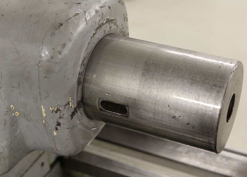
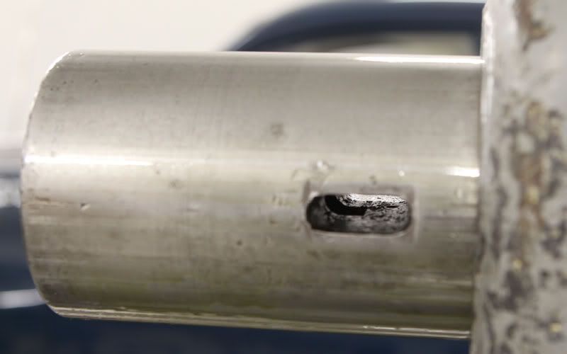
The other problem also had to do with the the same lever. The taper pin that holds it in position has been jammed into it's hole without the hole and the slot in the shaft being aligned. Result on the pin can be seen in the pictures. Either the pin was the wrong one as I could almost knock it through either way, or the hole had been enlarged due to the abuse. Either way: I made a new taper pin from a 10.9 bolt and everything lined up much better than before. Still I would like the gears to mesh closer, so I think I will take it apart again to see if I can align the change lever slightly different.
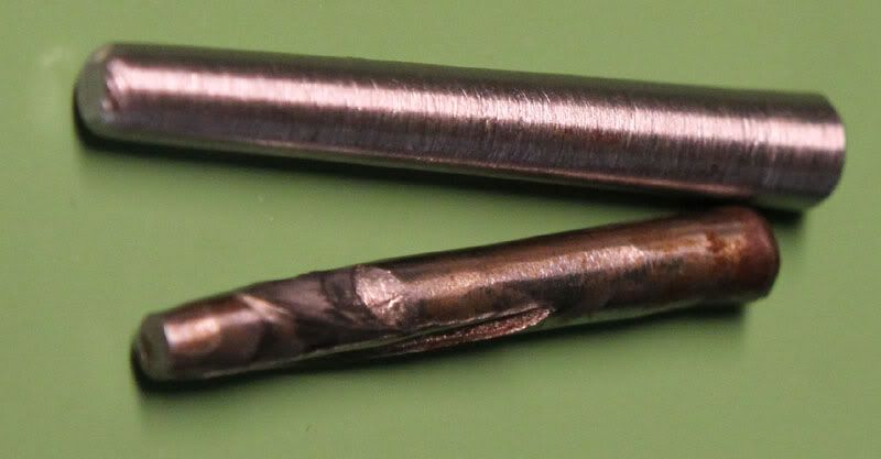
New and old pin:
Pace-018-B.jpg


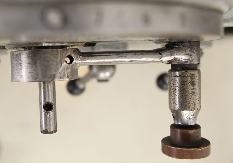
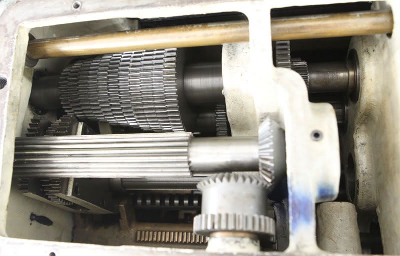
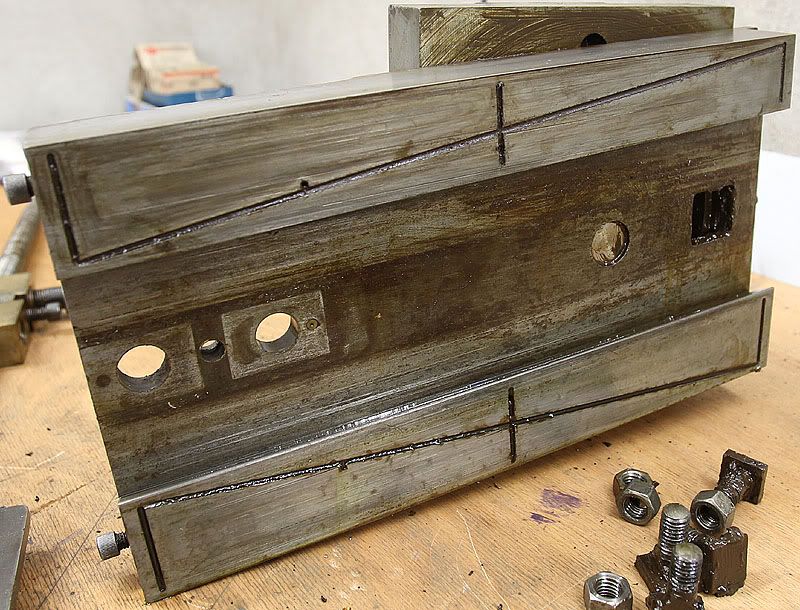
Here is the inside of the feed gearbox. The tumbler moves the gear in the lower left corner left and right, via the bronze rack at the bottom, to the selected gear.
The change lever rotates the gear in the front middle of the picture which in turn rotates the shaft and moves the gear in and out of engagement.
Pace-019.jpg


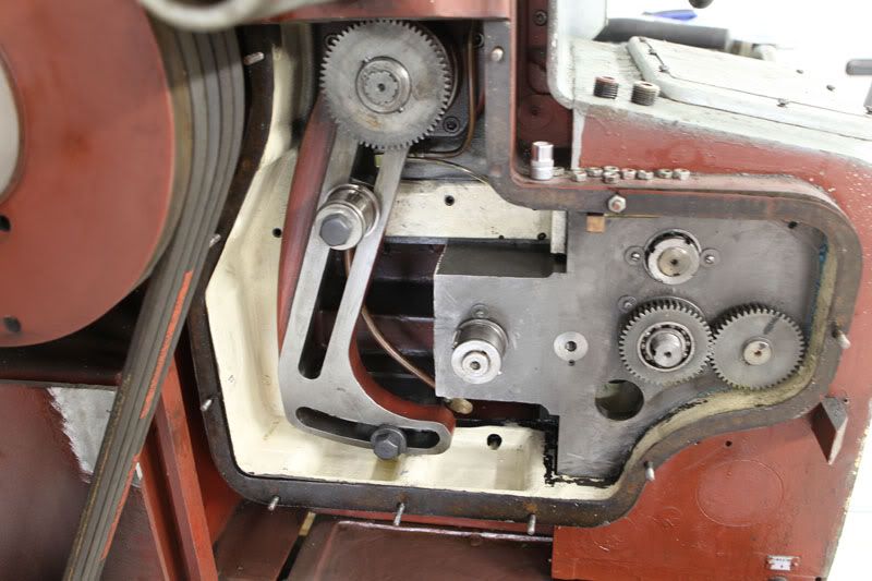
Here is where the change gears are supposed to sit. It had a lot of black sludge at the bottom (before I cleaned it up). Will take a picture of the gears another day. One of them have severe wear.
Pace-020.jpg


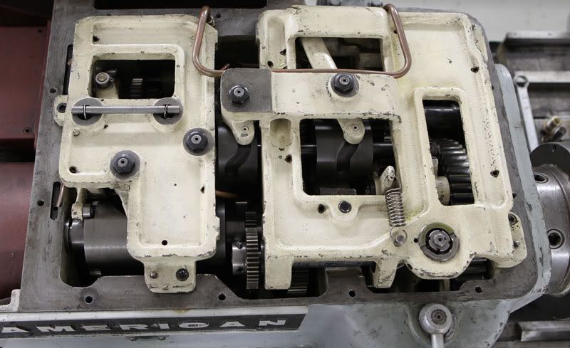
Headstock. The picture doesn't do it any justice at all. Maybe I'll take another one with a reference object included.
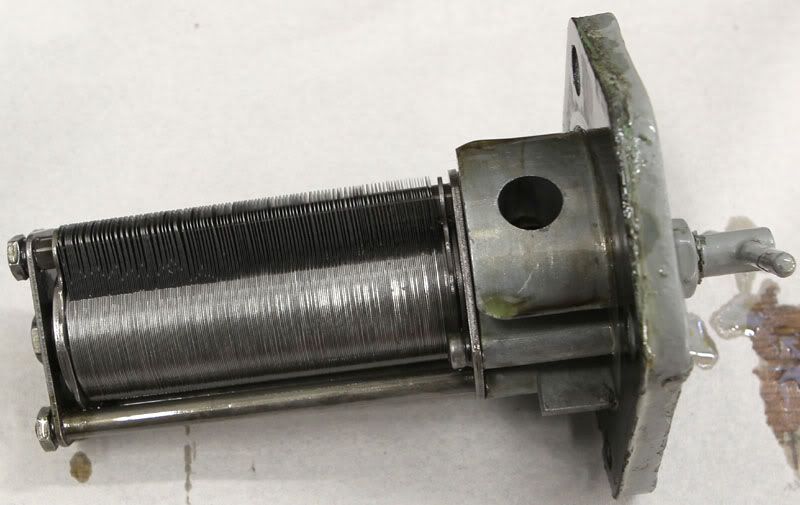
Pace-021.jpg


Oil filter:
Pace-022.jpg
 
I have some general questions.

The machine has been repainted at least 2 times (probably more) and I can't quite figure out what the original color was. It was either something similar to the grey it is now, or it was a green color similar to Reseda green. What makes me wonder is that the green color seems to have been applied in more places than the grey. What is the color code of the grey ATW used anyway ? Not that painting is on top of the priority list.

I finally got a price for the taper attachment bearings, and they are certainly not cheap: £25.80 ~ $40 EACH. So $805 total + shipping. If anyone know where I could possibly get them cheaper I would be very happy. The part number is 38KVLL2. I think both Timken and Fafnir makes them.

When I looked at the oiling system for the cross slide I started to wonder why they made it that way. There is only one oil supply from the pump in the apron, and it goes to the right dovetail, then through the cross slide over to the other side. This obviously leads to less oil on the side that is closest to the chuck. That side also gets much more chips on it, and it has more wear than the right side. I wonder why there isn't a separate oilsupply to each side ? Maybe I have overlooked something obvious ?
Here is a picture of the underside of the cross slide. It seems that there is contact in the center part too. If it is contact;is it better to machine down the pictured part or the saddle ?

Pace-013.jpg
 
Also, remove the screws that plug the oil gallleys in the carriage and slides, the, take a welding rod or straight length of coathanger and run the holes out, then blow out with air to remove gummed up plugs. Keep in mind that this lathe was designed and intended to be run like a modern day CNC.... ALL DAY, EVERY DAY. The oil plungers were to be operated constantly, which prevented them draining completely and running dry. To get full oil to the one at the pump shop after a few days of running other machines, I had to pump the plunger fifteen times or so to load up both the front and back carriage ways, as well as the cross slide.
 
Yes, it makes sense that the chuck side is the worst, but even if it is a pressure system I would have thought it would be better to have the oil go to the side with most wear-potential first.
I'll have a look at the oiling system, and see if any metering units are clogged. Should be easy enough to clean the galleys I hope.
I have oil to the ways of the cross slide with 3-4 pulls on the oil-plunger/pump. But I wonder if the plunger is worn or something because the only way it works is to hold it out for a few seconds and then let go..

There is good news regarding a few of the missing parts (I hope). The seller has sent me a package with some items. I hope it contains the taper attachment bracket at least.
 
It's difficult to read this and not tear apart my old heavyweight to clean out it's gunk. I know the oiling system's not 100% in it, but I cannot possibly afford the time to have it down to disassemble the carraige, crosslide, taper attachment, clean everything, order new oiling orifices and reassemble it all. I keep it well oiled and hope there won't be much damage using it until a time when I have a backup machine and can have it down for a couple weeks.
 
Great news: Yesterday I got a package, actually a wooden box, from the seller containing most of what was missing: Bed bracket, clamps and nuts for taper attachment, clamp nuts for tailstock and the height adjustment bracket and pin for the motor.

Regarding the paint: Since some parts are cleaned up I thought I'd try to figure out which paint color I want. I looked at the RAL-color website and decided 7035 (Light grey) looked good. Went to where they mix paint and looked at a color chart and figured 7040 (Window grey) was more machine grey.
Tested it on the bracket today and what a difference from the charts... Ended up almost white :eek:
I wonder if Graphite or Granite grey would be more like it ? Here is the website RAL Color Chart | www.RALcolor.com.
I will be happy for any suggestions.
The safe bet is always Reseda green but I think a lathe like this in Reseda green will be just too much of a good thing.

Garwood: I'm glad I have another lathe!


Back
Top