What's new
What's new

Our new American pacemaker lathe - Ongoing cleanup.

Today I was in the city and figured I’d buy the electric cable I needed to wire up the machine. $100 for 4 meters.. :O
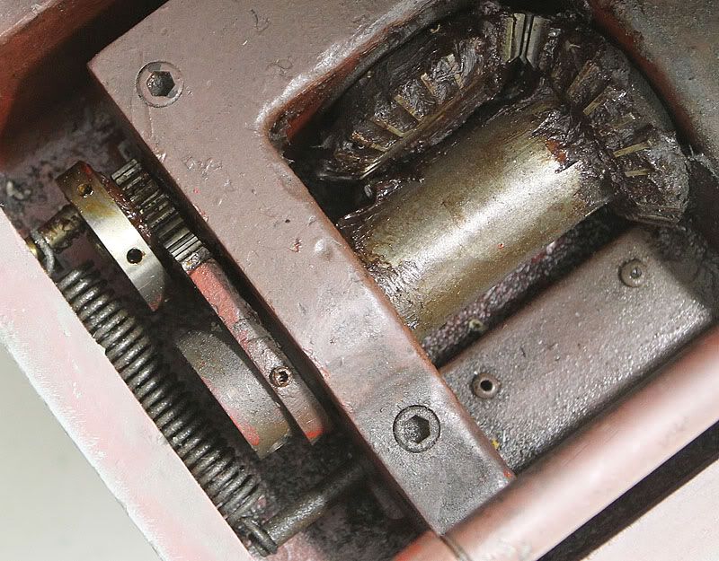
After connecting the wires, with great excitement I pushed the power button but nothing happened except a low hum. Starting to wonder if it has been rewired to 400V even if all the documentation says 230V. Something is definetly not right but I’m not an electrician so any ideas to what could be wrong is very welcome.

UNC bolts are not easily available over here but I think I have been able to find all the missing bolts from 3 suppliers in the UK. Even the low-head socket head bolts for the feed-box cover. We’ll know when they show up.

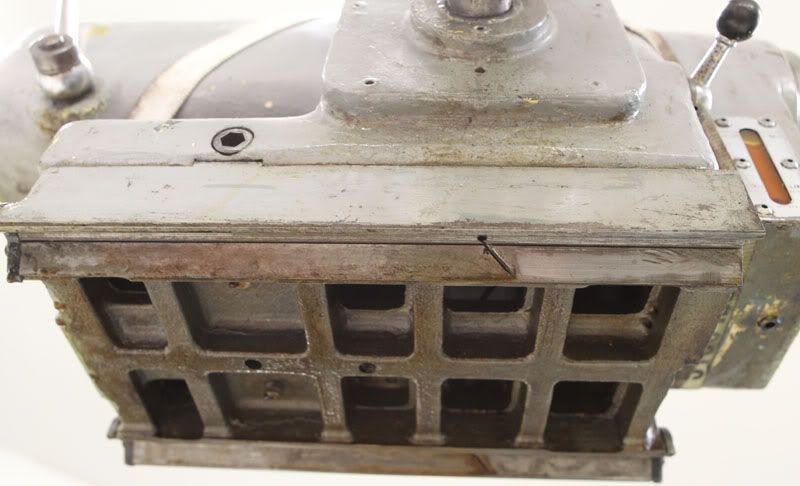
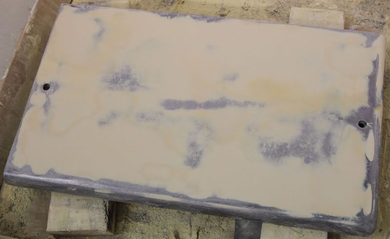
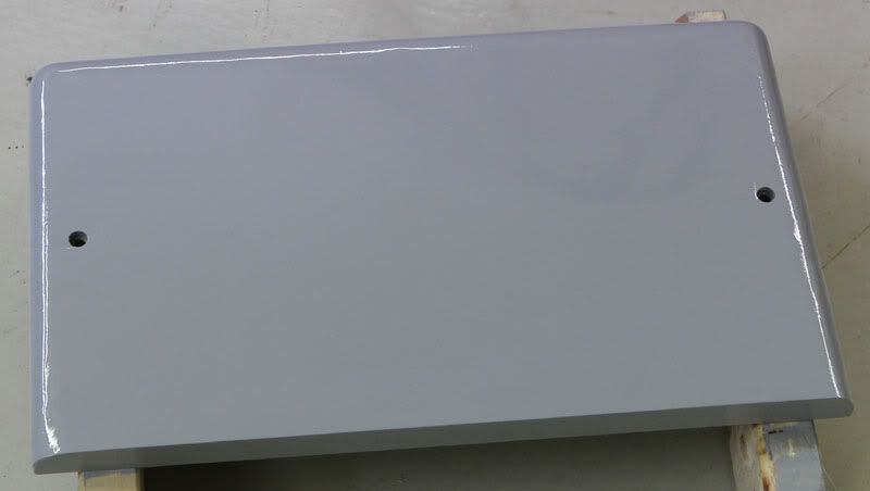
Regarding the paint i changed my mind about not painting yet for two reasons: Kind of stalled on some of the mechanical side because I am waiting for a number for bolts. The old paint is really hard to clean because it is so worn. So I’ll paint parts as I go along. Here are the covers in front of the height adjustment nuts. First I sanded down the old paint so only low parts were left, then used wurth Combi-let body filler. Not sure how many coats of paint I need but I wet-sand the first coat back to get it a bit flatter so probably 3 coats.
Pace-023.jpg


Pace-024.jpg


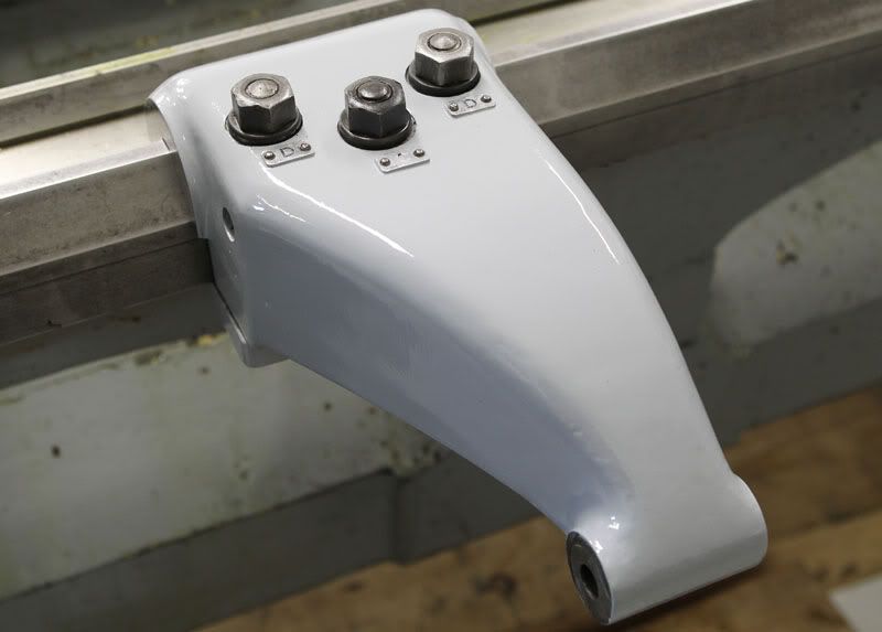
Here are the newly arrived parts:
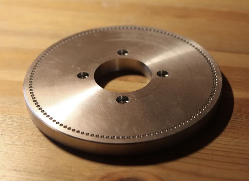
Bed bracket for the taper attachment. I cleaned and painted this as it is good to go. It is the same paint as the covers, even if it doesn't look that way.
Pace-025.jpg


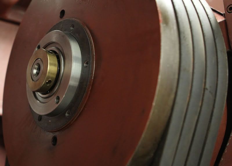
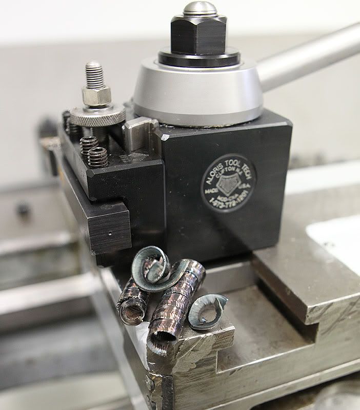
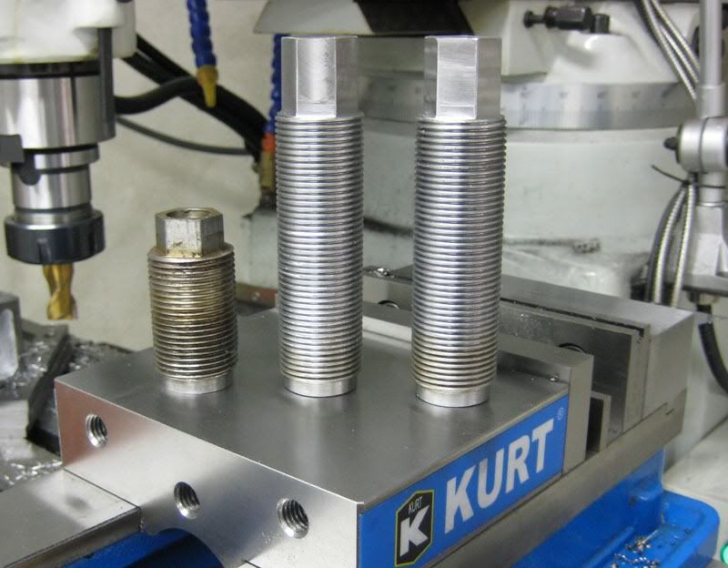
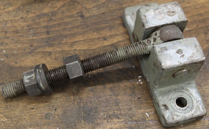
Height adjustment for motor or drive belt tension adjuster as you might also call it:
Pace-026.jpg
 
Clutch and tailstock base

First: I lifted of the tailstock and the state of the slides is less than perfect. It looks like they have been repaired with some kind of Turcite or some similar material, but either it was done improperly or 99% of it has worn away. It is down to the metal again on the right side of the closest slide in the picture and on a similar portion of the other slide. It definitely needs to be scraped, but we will see how bad it is when I take some test cuts.
Strange wear:
Pace-032.jpg


Over to the clutch issue: The clutch is engaged in both positions of the clutch lever (spindle rotates in both positions). I first thought the clutch was adjusted too tight (first picture belove) but after looking at the clutch (second picture) it seem like the linkage is not adjusted correctly because the fingers never release properly. In the picture they are as far as they will go with the current linkage adjustment. There is more than 1/2" of room for it to move to the other side though, and there is wear marks from the fingers much further out than they will go now.
EDIT: The gear and spring mechanism in the last picture was adjusted out of mesh, but just so much out that the gear blocked the gear on the linkage and prevented it from moving through it's full range. Wonder for how long it has been run with the clutch permanently engaged.. Still not sure which way the spring is supposed to hold the clutch lever.

Pace-034.jpg


Pace-035.jpg


Maybe this item will be clear when the clutch is in the correct position. It is a spring that holds the clutch lever in engaged of neutral. Difficult to say which as someone has made it not engage the gear that connects to the spring..
Pace-033.jpg
 
Last edited:
Pacemaker clutch works backwards to most. You push the handle downward to engage and towards the machine to release. Had to think about it for a second until I remembered how the one at the pump shop would mash your hand between the homebrew thread dial and the handle if you weren't paying attention and slammed the clutch out. Clutch is an over center setup. You push down until you feel it lock in place in a detent, and then you can turn loose. Pushing towards the machine on the clutch works as a brake. The clutch adjustment is VERY sensitive. A small fraction of a turn can be the difference between no engagement, proper operation, and full locked at all times.
 
Thanks again Mike ! The clutch works as you describe but I am very unsure if there any braking action. Since the lever can mash your hand when it goes up it seems obvious that the spring is supposed to hold it in th UP or brake position. I will try it that way.
Regarding the clutch adjustment: Am I correct in assuming that the larger outer steel ring is the adjustment and the brass nut is the lock for the adjustment ? If such is the case I need to make a huge pin spanner. If I have no brake that is.
 
There was very little spring pressure, if any, with the clutch disengaged. Only when you dropped it into engagement did you feel resistance, and that was more a feel of the clutch going over center, not a spring to overcome. The braking action is not very heavy. Helps to slow down, but will not slam the chuck to a screeching halt, much less a big piece of work spun up fast. Braking requires a definite, deliberate push towards the machine. It is nothing like a Nardini where the chuck screeches to a halt instantly.

The lever mashing the hand was a result of inertia, as you absent mindedly snatched the lever towards the machine while holding the lever. That machine had a lot of slop in the clutch lever and a home made thread dial that was oversized and hung on the wrong side of the mounting bolt. The proper thread dial and/or a properly fitting clutch lever on the square clutch shaft would not have trapped your hand.
 
After the electric issues were cleared away I actually made some chips. Didn't have much scrap to run test cuts on but I made some cuts about 1/4" deep with 1/32 feed - The metal peeled away like butter :willy_nilly:
I will take pictures and maybe a video when I get something suitable to machine.
One issue I noticed is the feed reverse lever is not working as it should. Now I am talking about the lever on the upper right hand side of the apron, not the lever with forward-Neutraul-Reverse on the bottom of the apron.
When I move the lever sometimes it engages and sometimes it doesn't (mostly not). I hear something moving inside the headstock but I haven't figured out what is wrong and where. Any ideas would be welcome. I have looked at parts Bulletin #20 1968 but could not fin the issue or the parts...

Regarding the main clutch lever: Is it supposed to have dedents in addition to sping loading ? If so: Where are those dedents ?
 
Been so long since I was around it, I can't remember the exact setup of the clutch system. It probably does have detents, but it sounds like somebody has been playing around in there.

If they took some of the clutch linkage loose and didn't get it timed properly, the detents may engage in the wrong position or not at all. The one at the pump shop slipped out of gear occasionally at some speeds and the leadscrew reverse to cut left hand threads didn't work. Somebody had been inside and flipped the idler gear for reverse backwards to where it did not engage. About a fifteen minute fix. While in there, I found the six speed shifter quadrant out of time, maybe a half hour fix. Also a weak spring (somebody replaced it with an inferior part) on the quadrant that provided detents.

Point being, get in there and look around. Although complex, these machines are not insanely complicated like a German Meuser or something. It is all very simple straight forward mechanical bits.... just a lot of them. All timed gears are marked with punch marks or some kind of lineup marks to keep it all working right. Some folks are just not bright enough to pay attention and put it back together right.
 
Thanks again for your comments Mike, very helpful !
The main clutch linkage works as it should now. There is no dedents, but the spring I mentioned earlier holds it against both the brake and the engaged/in.
Here's a picture of how the spring is supposed to be set, to act both ways. As I have set it now it has very slightly more pull towards the brake position, which I am happy with.
Pace-037.jpg


Here's a little video of the movement of the linkage: American Tool Works main clutch linkage - YouTube

As I mentioned I have made some chips. I only had a little bit of scrap to play with but here are the results (Aloris CXA in background):
Pace-036.jpg


I think I have identified the problem with the leadscrew reverse, with the help of a nice gentleman on the forum:
One of the dog teeth is too damaged or plain broken off to allow enough torque transfer to move the screw.
If the clutch shaft for the leadscrew is as deep in the headstock as we suspect I will have to use the traditional method of threading for a while, as i am not ready to tear down the whole headstock right now.
 
Glad I could be of help. If I was in your locale, I'd be elbow deep in that old beast just for the fun of it. They are incredible machines in terms of rigidity, power and accuracy. Sure wish I had one where I work now. The Takang I am running sucks.

You haven't even got its attention yet, lol. The guy I got the 20" Pacemaker from when he donated it to the museum said he had a regular job he ran on it that was mild steel, 8" in diam. Don't remember the feedrate (if he mentioned it), but I do remember he said he was running 5/8" depth of cut. That lathe only had four of the eight belts installed. I have done almost 3/4" deep in 316 stainless with a trigon insert cutter. Only reason it wouldn't cut deeper is that was all the edge on the insert. You will chicken out before you hurt the machine. The limits on removal on these machines is almost always the work or the tooling. You'll run into chatter before you hit the machine's limits.
 
Made the two leveling bolts I was missing. I was missing two of the long ones for the rear of the headstock. The left one is one of the short ones for the front/tailstock end that came with the machine.

Pace-038.jpg


I'm also working on the gears for metric threading. I have made the blanks for 50 , 60 and 127tooth gears. 80 tooth gear still to go. And the cutting of the teeth of course.
I also made a 127 hole dividing plate (for obvious reasons). I made it out of 6061 T6 as it will get very limited use.

Pace-039.jpg
 
While doing some cleaning and painting at the tailstock end I took off the end-cover for the lead-screw. Underneath the cover there is provisions for adjusting leadscrew bearings by means of a nut on the end of the leadscrew. That was off course tightened with all the strength of the gorilla last adjusting the bearings, so I didn't adjust anything.
While I was in there I noticed a significant amount of end-to-end play in the leadscrew. I didn't measure it but I guess it is about 3/8". There were also some brass-shavings in there. I noticed there was "some" backlash when threading a week ago too, but did not investigate further at the time.
I wonder if the leadscrew should have any backlash at all (apart from clearance in the thrust bearings) ? It is certainly too much as it is now because the dogs at the headstock end will not engage the leadscrew at all when it is at one end of the endplay.

I am reading the book "Screwcutting in the lathe" now and I am at "Dog clutch control". The pacemaker has a leadscrew dog-clutch (which I am having issued with, as can be read further up) and the reading made me understand the operation of the clutch a little better I think. It seems to me that the clutch in the Pacemaker is one step further along compared to what is described in the book, as it will reverse automatically, not just stop the feed. So: When threading to a shoulder I assume I can just set a collar on the rod that controls the clutch and the leadscrew will reverse automatically at the exact same point every time when the carriage pushes the rod and throws the clutch ? No need for retracting the tool ?
Edit: When reading a little further it was all clear. When the carriage hits the stops the clutch is obviously moved to neutral. Very useful book though.
 
Last edited:
I have started on the chip-pan now. At a glance it seemed like the coolant-reservoir was cleaned out pretty well, but it definitely is not. The sump runs the whole length of the chip-pan but the drain into it is about 15" long. That leaves about 30" that I can't reach.
The stuff in there has been sitting for a few years I imagine. It is like a combination of tar and dirt about 1/2" thick. I was thinking of trying to flush it out with a high-pressure washer but I don't have one with hot water so I'm not sure it will do. Does anyone have any smart ideas on how to get everything out ?
Last resort is cutting another drain in the chip-pan. Pictures to come.
 
Dowel stick with "hoe" blade attached helped on the CW16 X 102 Monarch. Fortunately, those gents designed it so the covers (one of which had the big drain port) came off after removal of a hand full of flat head screws
 
Thanks !
I'll try those two ideas. Not sure if it's possible to get it all out that way since the dirt in there is so hard.
Today's work: Drag chip pan outside and cut out the bad pieces with angle grinder. Since I don't have oxy-acetylene there is no way to beat it into submission.
As can be seen in the following two pictures it is a little worse for wear. I have cut out the bad parts of the sides and welded in new ones today. The whole rear flat section will be a bigger task for another day. The seams are welded on the outside, probably to leave a smooth inside so dirt and chips have less chance to stick. It is easy to weld it that way too. I just leave the walls a little long and grind them down after welding.
I will probably have to cut out the rear wall along with the flat to be able to get the rolled edge semi-straight.

I wonder if the steel in the pan is heat treated in some way. I am welding in mild steel plate with the same thickness and when I persuade it with a hammer it bends much more easily that the original steel.


Heat-treat doubtful - sheet steel might want to act like a potato-chip. Rolling, stamping, bending to form it, OTOH, could easily have stiffened it.

Bill

And the original material might have been a carbon steel such as 1045 or such that was fabbed and left as-is (which would be stiffer than mild steel).
 
Thanks for the tips!
I am going to look at the clutch plates (seems worn), but I am not able to remove the cover / bearing cap that is just outside the plates.
It was fastened with 6 bolts which I removed easily. The inside pullers I have are not thin/narrow enough to get in there, and I am not sure it is a good idea to push against the shaft either..

Edit: Drilled and tapped two holes 1/2 UNC in the retainer and pulled it out. If I had looked at the drawing properly I'd known that that was not enough. I still need to pull the bearings and clutch disk housing too. But how..
 

Attachments

  • PMC1.jpg
    PMC1.jpg
    82.3 KB · Views: 424
Last edited:
Easy: Just screw the clutch adjustment nut back onto the shaft and use a bearing puller. The huge bearing, the two smaller bearings and the housing for the clutch discs comes out.
The huge bearings doesn't feel good at all: I have not dealt with huge open bearings like that before but it does not spin smoothly even if it looks ok and there is very little play. I am thinking I'll just get a new one, but it seems like a metric bearing 130mm OD and 25mm thickness. Strange ?
To the clutch discs: Anyone have any idea what the thickness should be when new ?
 
Clutch

I have now had a the clutch all apart.
I learned the following:
  • The original thickness for the clutch plates are 0.05" = 1,27mm. My plates was basically brand new.
  • I think it is possible to assemble the clutch wrongly.The driver plates, with the notches on the outside, is just flat so they can be put in any way you want. The driven plates that are notched on the inside have ground high and low parts. It seems to me you must have the highs and lows in the same position relative to the splines and the highs and lows on the same side on all the plates. The driven plates was put in randomly in my lathe and the clutch was slipping in high gear and there was no proper dedent when you moved the clutch lever. When I put everything back together again I put all the driven discs in the same orientation. What a difference it made: The adjustment is positive and 1/2 rotation on the adjuster makes it go from not engaged to "hard to engage". Before it took quite a number of seconds for the spindle to get up to speed in high gear. Now I have a different problem altogether: As I probably have mentioned before I have water heating pipes in the floor so I have not screwed the motor bracket to the floor. When engaging the clutch in high gear the motor lifts.. Guess I'll just have to feather the clutch a bit when engaging high gear, until I find a way to secure the motor bracket.
    I replaced the 75x130x25m bearing when I had it apart since it did not feel nice when I spun it. It is a deep groove bearing. I used SKF 6215 Exporer.

To take it apart:
  1. Loosen belt tension.
  2. Remove cover on belt pulley.
  3. Loosen grub screws on both clutch adjustment nut and pulley nut.
  4. Remove clutch adjustment nut.
  5. Remove nut that holds belt pulley on shaft. Put a piece of wood in between the belts and the motor pulley to lock the pulley if the nut is hard to remove.
  6. Remove belts.
  7. Use puller to remove pulley from shaft. There are two 1/2" holes in the pulley that are made for this.
  8. To remove bearing cap for 130mm bearing I drilled two 1/2 holes in the cap and removed it with puller. In hindsight that was a mistake, as you can remove the bearing cap and the clutch housing at the same time: After removing the pulley screw the pulley nut back onto the shaft and use a puller to pull the bearing cap out along with the clutch housing and bearings. This will pull the oil sling plate too.
  9. Remove cover over clutch engagement mechanism.


To put it back together:
  1. Clutch lever must be disengaged.
  2. Put all the clutch disks onto the shaft.
  3. Start sliding the clutch housing onto the shaft. When you come to the point when the clutch disks are about to enter the housing put a mirror in through the top opening and check that all the driver discs are entering the housing correctly. You can not see in there without a mirror.
  4. Put the oil sling plate onto the clutch housing.
  5. To seat the bearing cap it will be nice to have an assortment of different length bolts or lots of washers and 2 long bolts. With this you can pull the cap into position. Use sealant on the back side of the cap. If you don't it will leak.
  6. When putting the pulley back on it is vise to mark the position of the keys at the end of the clutch housing, as it is hard to see exactly where they are when you have started the pulley.
  7. Remove the 1/2" grub screw from the shaft and use 1/2" bolt and assortment of very large washers or something similar to press the pulley back onto the clutch housing.
  8. Put belts back on. Use wood piece and suitable tool to tighten pulley nut. Tighten grub screw.
  9. Put clutch adjustment nut back on and adjust to your preference. Tighten grub screw.
  10. Replace covers.
  11. Tighten belts if you have the motor adjustment bracket bolted to the floor.

I had planned to take pictures with it all apart but off course I forgot. I hope the text version will help someone.
 
I've wondered for a time if the dial on the tailstock is supposed to just move along with the quill with no way of resetting it to zero. Today I started cleaning it up and WD40 found it's way into the cracks. There was no way I was able to loosen it by hand, so with a suitable layer of protection between the dial and the waterpump-pliers it broke loose. The previous operator, Harold "Heavyhands" Johnsen, had a hang for tightening up everything real good it seems..
The dial is at least 8 pieces, including a brass bushing for the whole thing to turn on. There is also a brass bushing inside the dial itself. You know it is a proper piece of equipment when the dial on the tailstock has more parts than the apron of the average chinese lathe..


Back
Top