What's new
What's new

Overload protection on a RPC using multiple smaller motors

Brian Campbell

Plastic
Joined
Dec 14, 2021
Hello

I'm building a RPC to convert two legs of a three phase system I have coming in to my property into usable three phase power.

I live in New Zealand which has the same power supply as the UK and Australia. Having two legs of a three phase system is reasonably common on older rural property's in these countries.

There is another post I started about a month ago that thrashes this point to death, for better or worse it is what I have coming in to my property.

That being 230v phase to neutral and 400v between phases.


My two legs are from the same service, phases 120 degrees apart

-----------------------phase-1-------------I DONT HAVE------

-----------------------phase-2-------------I GOT-------------

-----------------------phase-3-------------I GOT-------------

-----------------------Neutral--------------I GOT-------------


I have decided to use four (3-4kw wye wound motors) instead of one large motor.

The reason for this is motor availability and the fact I can have a staggered start on each motor to avoid in rush current issues.

I will be using a siemens 24v dc transformer to power the four motor contactors. I will have a 32a 3 pole cicuit breaker on the main power coming in.

The issue Im having is how to protect the motors individually from overload. Past posts have mentioned typical motor over loads such as Allen Bradley E1 plus wont work as they fault on unbalanced load with a rpc invariably has.

The four motors im using are not identical, they have full load amps on the name plate as follows.

Motor 1 4.8a

motor 2 5.2a

motor 3 7.5a

motor 4 8a

Please find attached a schematic of how I plan to hook up the components I have.

I just would like opinions on were to place overloads and what type to use

Thanks, Brian

cad motors.jpg
 
Last edited:
Change the contactors to starters (contactor + ol relay = starter). One ol per motor. Type of ol is another matter. Old days, the ol's didn't have phase loss/unbalance protection. Now almost all have this feature. You may have to go to your local electrical distributor/motor shop for this.

Tom
 
Must be nice to have a automatic phase shift on one of your incoming's so that no start capacitors are needed.

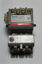
I would get the same overload for all four locations. Like this one with an adjustment range. The overload detaches and can be used by itself.
Better to get four complete contact/overload devices. The new ones these days are half the size and way more expensive.

If you want to use your existing contactors then find what overload devices accompany them. If they use the old style metal heater strips then
you will need four sets of heaters. And those type units have a limited adjustment range from 85% to 115%.

I run the generated phase up thru the third hole in my overload device, like the one in the picture. To avoid phase loss trips.

DSC_0806.jpg
 
Thanks for the replies

As two motors have 5 amp draw at full load Im thinking of powering two motors through one 10a mcb pictured

982280733.jpg

The other two motors have a combined full load amp draw of around 16a so am thinking of running them through an mcb of 16a.

As the motors will be staggered in there starting I am hoping a c curve breaker will be ok. I know its not an ideal way to do it but is the best I can come up with at the moment if conventional modern motor overloads are out of the question due to phase imbalance.

With only using two phases and a neutral to run the idler motors would you expect higher amps than the name plate indicates?
 
I do not see how having two motors off of one protection device set for 2 x the FLA will provide protection- especially with a staggered start.

They are idlers. The only time they will be at or above FLA is when being started- and they are designed to allow this.

I would not assume modern overloads are out of the question. You need to determine for each device being considered how much imbalance and how long does it need to exist before it trips. This information should be in the technical information. As Rons suggests, run the generated leg through the protection device. For example, I am using an Eaton XTOE100GGSS. It trips on a 50% phase loss imbalance. That means that for my 250 volt system one leg needs to be pulled down to 120 volts. That is a lot of imbalance. There will also be a time delay as the monitor powers up, and some time allowed for an imbalance to exist. The AB E1 Plus says 3 seconds- but I could not find the % imbalance required to trip.

Remember that only the first idler you start will be starting on 2 of the 3 phases, The other 3 will be starting on 3 phase provided by the ones already started. If you want to be cautious buy just one modern device and hook it up to one idler and try it.
If you do have a problem starting the first idler due to the protection tripping, switch and use the old thermal breakers. Use the newer device for the the 2nd, 3rd or 4th idler.

Regarding your question about higher current from starting on 2 of 3 phases. The inrush current and idler current will be higher- but you will be well under the FLA with the idlers. Single phase to 3 phase power input has the single phase power multiplied by 1.732. In other words a 10 amp 3 phase load run by single phase requires 17.32 amps. I do not know what it would be for your system- other than less than that.
 
Thanks for the reply Thiele

I like your idea of using a thermal breaker on the first motor and then using proper motor overloads on the other three.

I didn't realize some could tolerate such a large phase imbalance(50% for the Eaton one you mentioned), from what I have seen most manufacturers don't actually list the phase imbalance need to trip but just say they have "phase loss protection".

Are most modern motor overloads set by measuring the amps drawn under normal conditions and then setting the overload at a fraction higher than the measured current? i.e they are never actually set to the full load amps on the motor nameplate.

I will put some photos up soon of overloads I have available
 
I realise now that overloads are set using the service factor multiplied by the FLA.

For the thermal overload on the first motor is there any advantage of having a specific "thermal motor overload" versus a miniature circuit breaker of the same amps?

If I understand correctly they both use bimetallic strips to disconnect with sustained overload, do the "motor" overloads have characteristics that make them better suited than a minature circuit breakers? or is it just the fact the amps can be dialled in exactly on a "motor" overload? In my case I have a mcb that is the exact correct amps.
 
With a miniature circuit breaker you would need to see if it is rated for use with an AC motor. These will allow for the inrush current, which will be much greater than the rated amps--but for a short time. With a non motor load that allowed overcurrent would
destroy the system being protected.

Some motor rated devices use a bi-metalic strip, but others use a eutectic alloy with a selected melting point. When the alloy melts it allows a pawl to turn, and this trips the contact open.

What are Cable Carriers? Summary for Motion Engineers

They are available for different classes- but do require compensation for ambient temperature. The link below tells you all you would want to know regarding the Allen Bradley versions. They will not be "exact" - but they do not need to be. They were what was used for at least a half a century.

https://literature.rockwellautomation.com/idc/groups/literature/documents/td/592-td010_-en-p.pdf


In protecting the idlers you do not need be exact in the ratings regarding the service factor and FLA. It is an idler. It will have no mechanical load unless a bearing goes out.
 
Thanks for the reply and links Thiele

I will use a proper thermal motor overload on the first motor.

As for using Allen Bradley E1 Plus overloads on the other motors, is the consensus this will be ok?

These three motors will have there star points connected to neutral and will be contributing to help generate the third leg, I would imagine the amps through each phase will vary widely.

Do these overloads simply measure voltage on each phase to determine if one has dropped out? If so then It should be ok as the first motor will be helping

If they measure amps through each phase and then trip based on a large differential I don't imagine they will work
 
I looked online to see what I could find about the E1 and E1 plus overloads. All I could find about their phase loss system is they typically trip in 3 seconds.

I did find useful information on the E3. With it you can disable the phase loss detection. You can also set the time delay until trip from .1 to 25 seconds.

Here is a link to the information. Its on page 3, top right.

http://bph.hsph.harvard.edu/datasheets/Allen-Bradley-193-td012-en-p.pdf


Back
Top