What's new
What's new

Parker/Eurotherm 514C/507 4Q SSD DC Retrofit into 1961 10EE Modular

In this "State of the World" I'm up for almost anything... Parts are hard to find and even when I find them I have to figure out what they are!

Maybe we should talk....:)

Welll. A tad DEAF! But we can email!

There's time. And then there is money.

I spend rather a lot on this sort of shite. Because I still can. And have been pushing electrons and accumulating the goods since ....Truman was still President.

Time is harder nowadays.

I need to start off-loading more of this or it will NEVER get done.

I have an offer in on a 514C-32 board now... See if they agree....

I am looking at things a little different this month... Two weeks since I survived the "Widow Maker" and time suddenly has more meaning for me... I'll PM you my email....
 
I have an offer in on a 514C-32 board now... See if they agree....

I am looking at things a little different this month... Two weeks since I survived the "Widow Maker" and time suddenly has more meaning for me... I'll PM you my email....

"board" is useless. Too sophisticated for a board-level repair project.

The big MOV alone is close to a hundred bucks as a repair part.

You want a full package, known working-order, nothing less.

They just aren't all that dear, brand-new, full warranty.
About the same as or less than the typical bench repair minimum for the class of goods.

"hourly human" vs "magazine" fed automated PCB stuffer thing.

Responded to your email.

More later.
 
Help trouble shooting the 514C

I finally have my retrofit DC control system complete and need some help to trouble shoot why the 514C will not power the armature circuit. I have read the manual many times and followed the advice and schematics in this thread diligently. To give some background I'll run down the components used below.

  • 30A 240VAC mains circuit feeding the entire system
  • 338VAC supplied to L1/L2 on 514C via boosted isolation transformers
  • 20mH choke on the armature circuit
  • 15mH choke on the field circuit
  • Parker 514C controller powering the motor armature
  • Eurotherm 507 controller powering the motor field windings

The motor and all wiring to it has been tested to work. If I connect the armature leads to an external DC voltage the motor turns smoothly. The 507 controller works fine and varies the field voltage from 20VDC to a max of 120VDC using the field weakening potentiometer.

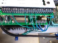
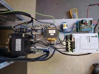
The 514C powers up and LED L1 lights up. When I engage "RUN" mode, LED L4 lights up but no voltage is output on the A+/A- terminals. I am reading the correct voltages at terminals T14, T16, and T24. However, T19 should be reading around 24VDC to indicate the system is healthy and it is reading 0VDC. There is not much in the manual about the "Health" reading but it must be that something is not right.

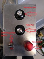
Below are pics of the terminal connections, switch settings and general layout.

Any trouble shooting advise is welcome! I just hope it's not a bum controller :(


terminals.jpg switches.jpg system.jpg
control_box.jpg
 
your connections look correct.
as long as 20-24 is jumpered for ENABLE and 5-24 for RUN and 11-22 for HEALTH, you should have output from A+ and A- for armature as long as your pots are wired correctly and calling for speed setpoint >0.
let me review your connections and give it some thought...

try jumpering T13 and T14 to bypass the pot.

I am not running a tachogenerator and forgot to jumper from T11 to T22. That did the trick!

Thanks for the extra set of eyes and check of the basics.
 
I understand the pot for controlling the 514 and mains DC for motor. Why and what is the 507 and "field" for? I have a 1954 monarch and am willing to change to this drive. Just need help understanding some of it.
And is the choke hooked to what? Is it a single line choke?
Thanks.
 
I understand the pot for controlling the 514 and mains DC for motor. Why and what is the 507 and "field" for? I have a 1954 monarch and am willing to change to this drive. Just need help understanding some of it.
And is the choke hooked to what? Is it a single line choke?
Thanks.

This is pretty thoroughly explained in the first page of this thread. I would suggest re-reading it, but to quickly recap. The 507 controller is used to supply a varying voltage to the field coils of the DC motor. This is how the 10EE is able to increase its RPM above the base motor rating.

For example: The 3hp large frame Reliance motor that came in early round dial machines was rated at 690 RPM when supplied with 230 VDC to the armature and 115 VDC to the field coils (i.e. full voltage to both). But when you lower the voltage to the field coils while keeping the voltage at maximum to the armature, the motor will spin up to 2,400 RPM (and higher). This combined with the right pulley ratios is why the 10EE can achieve anywhere between 2,500-4,000 RPM spindle speeds.

The choke is simply a large inductor that is place in series with the DC armature wiring. It is not required, but is highly recommended.
 
The choke is simply a large inductor that is place in series with the DC armature wiring. It is not required, but is highly recommended.

Actually.. it IS "required".

It was absent on the OEM MG because the DC generator's "rotating power" has near-zero lumpiness in its DC output.

For motors powered from "RECTIFIED" power where there are either full sine-waves or - far WORSE - only PARTIAL ones, even the purpose-built "RECTIFIED Power Motor" (RPM) line (Reliance name for it..) are specified right on their datasheets as requiring a "ripple filter" AKA "DC choke" for any winding above 180 VDC.

The 180 and 90 Volters have so damned much Iron and copper in them they can "get by", but still benefit from a choke.

Same again, the DC DRIVE makers specify use of a ripple filter for the type of application the motor represents.

In addition, all the OEM DC motors Monarch utilized PRE-DATE "Rectified Power Motor" era - which entailed very significant re-engineering.

"RPM" motors (Reliance published a 'white paper" on it) don't just have higher Voltage insulation to resist spikes and corona discharge piercing.

The whole concept shifted to "lamination-frame" design with a new lamination shape. Re-designed to better deal with energy transfer from a pulsed DC source.

More to it than "SCR Duty" wire/insulation, shaft grounding...

Note that GE DC motors, present era (made in China by the new owner of the name) also use the same squarish (Octagonal, actually) lamination-frame as a Reliance RPM I, RPM II, RPM III et al pioneered over fifty years ago by now.

So if nothing else, even if you don't mind the 120 Hz "growl", the older motors ALSO need the choke to reduce risk of damage from a fast-switching DC Drive's spikes.

Fast-rise pulses @ 120 per second (single-phase DC drive) or @ 360 per second (3-phase DC Drive) the entire time the motor is ON, beat the leaping shite out of a motor compared to the odd contactor opening "stop" spike .... hitting about a tenth of a percent as often.

Now.. one CAN "do that" protection of the (scarce and COSTLY) DC motor part with a lesser-value DC choke than the 12 to 20 mH ones I use and recommend.

Even a 20 MICRO Henry will knock the sharp edges off and spike-proof an old (scarce and COSTLY) DC motor.

The larger values do more.

- They smooth the running.
Bigtime.

- They extend the lower end of the useful RPM range, "direct" drive or reduction-geared.
"Bigtime".

One revolution in fifteen seconds (1/4 RPM) in reduction gear is a parlour trick. Guilty as charged.

2 RPM to 2400 RPM 'stepless' in direct-drive, OTOH, is actually useful.
 
Uhhh - 4 rpm? 1/4 RPM would be one rev in 4 minutes

Sorry.. one rev in four MINUTES it was. And a bit. I suspect I can go slower?

But I didn't have the patience to measure it beyond six or so.. as that was when I discovered the 514C-16 analog logic "AT ZERO" sensing goodies had sort of an analog "memory" to it and got sidetracked to playing with a different "parlour trick".

- Command a STOP.

- Before acting on the "I am AT the commanded zero RPM, thanks", signal the drive generates, (useful for "Field Economizer", for example.. if one wants that)

...grasp the workholder and move the spindle. Either direction off the position it stopped in.

The bugger moves BACK to its prior position. From either direction.

This is where the extra Bournes ten-turn trimpot enters w/r "tuning" the zero-set of the gross-motion potentiometer.

So it does NOT "creep". And... getting clever with "creep", rather than jog when one WANTS it to do.

None of which features a 10EE actually has much real-world USE for, but still...

I'm only into it for the Halibut, not for the chips..

:D
 
Now that I have replaced the spindle in the 1990 10 ee I need to start on the electronics. Is the a parts list or diagram for this conversion?

Mark posted a couple of google drive links where the print can be viewed and downloaded. It can look small at first, but when you click "download" it expands nicely. Those two links:
514C_507 Wiring Schematic_PRINT.V1.3.pdf - Google Диск

302 Moved

He posted here if that don't work:
Parker/Eurotherm 514C/507 4Q SSD DC Retrofit into 1961 10EE Modular

And I broke into a few larger pieces here:
Parker/Eurotherm 514C/507 4Q SSD DC Retrofit into 1961 10EE Modular

The actual parts list you probably want Mark and Bill H to help with.
 
Now that I have replaced the spindle in the 1990 10 ee I need to start on the electronics. Is the a parts list or diagram for this conversion?

It's pretty informal. The "basics" are in this very thread, basically "simplified" after (at least) five readings (each) of the SSD manuals! See footnote.

.. but each of us then, since, (and the several who went before, write-up or not..) have never been 100% identical as to choice of boost transformer (array), protective devices, potentiometers used, "ripple filter" choke...

Even Mark's and mine - done as a joint effort with a short ton of out-of-band emails - share the basic DC Drive "commissioning" option settings - which might seem odd, given I'm using the 3 HP "Large Frame" Reliance while he has the 5 HP GE KineMatic...

.. but we made different potentiometer, control switch/relay, fuse/circuit breaker, transformer, and choke choices.

"By the book" (Parker-SSD manual...) as to such goods needed...

And then..

The two most crucial parameters to satisfy for success are:

(A) Enough AC boost into the SSD. 320 to 350 VAC is a good target, and at 5 to 7 KVA.
Anything less, stability/load regulation suffers, even if not asking for full power.

(B) Enough ripple-filter in series on the DC output as to both Amps and inductance.

-- The Hammond is 20 Milli-not-Micro Henry @ 20 A.

-- The Lenze "swinging choke" I also use is 16A and variable inductance.

Anything MUCH less, audible noise at the final-drive motor goes up. Which is also audio frequency vibration (120 Hz, as a pronounced "growl" under hard accel or braking) in the drivetrain - potentially showing-up in the surface finish.

Which may not matter to most folk, but still...

When you have BOTH satisfied, you get a smooth running 10EE, FULL power (and a bit more on the 3 HP ones.. ~ 4.3 to 4.6 HP..) and a wider usable power-band than OEM.

(NB: I also use a filter choke on my FIELD supply, run at a 140 VDC max...)

The smooth LOW end is kinda awesome!

Do you NEED extended low-end? Well.. not for "collet running" & "carbides", no.

Then again, I'm an HSS/Cobalt // Stellite/Tantung-G guy. NOT carbides.

Annnnnd ALSO have several faceplates up to 11" and chucks 4" to 10"..as well as 5C, 2J, Rubberflex 9XX, Burnerd Multisize, ER and TG....

Keeping in mind that we don't run a 10EE at FULL load often if EVER, and that with such a short bed, even the final-drive motor gets a rest on the backhaul often enough Monarch didn't need to buy "Continuous Duty" motors....

If the 20 Amp, 20 mH Hammond choke (about $300, new) is hard to get into the budget, (only the 5 HP motor really needs that much Ampacity..) there are some "Rex" 17 mH @ 16A as show up, used, now and then.

My rare Lenze is even lesser Ampacity, but just fine for the "nominal 3 HP" motor, even pushed to a (calculated) max of around 4.6 HP.

NOTE: The Manual is complex because Shackelton Designed their "SSD" DC Drives as sort of "universal". They can be "Commissioned" or "option configured" to do almost anything that CAN be done with a single-phase DC drive.

What we do to run a 10EE is actually dirt-simple. But if Mark had not published this thread to pick-out the "meat", and if others had not also contributed, it would be all too easy to get sidetracked.

For a long time. "DAMHIKT!"
 
I have a question: between 7 and 14 is that a 100k resistor placed? Which wattage 100k resistor is used?
Thank you all for sharing this clever solution to the Monarch drive replacement
Steve
 
I have a question: between 7 and 14 is that a 100k resistor placed? Which wattage 100k resistor is used?
Thank you all for sharing this clever solution to the Monarch drive replacement
Steve
If your referring to the schematics posted in this thread previously, then that is an optional circuit. It is used to allow 150% over-current to happen for a short period of time. If needed, the wattage is really not critical as it is for signaling only.

If your using a 3hp motor it is not needed. I do not run it in my setup and do not have any issues. The OP needed it because they are potentially taxing the drive by running a 5hp motor, so I guess it depends on your setup.

Definitely read the Parker manual before doing this conversion. It has all the information needed, albeit critic at times.


Back
Top