What's new
What's new

PILZ PNOZ operation - how does it work?

swarf_rat

Titanium
Joined
Feb 24, 2004
Location
Napa, CA
I hadn't used my DMC63V for awhile and when I powered it up I get axis errors as soon as I try to enable the 24V (HH426 control). I have all the documentation but the E-Stop chain is ver obscure and complicated. It involves a PILZ PNOZ1 and a PILZ PZE5V8 expansion along with about 13 other (mostly Seimens) relays in series. There is also feedback through the control and through the axis drive.

In trying to understand what is wrong, I've been looking at the PILZ relays. Their documentation is really bad, and these are wired nothing like the rudimentary examples given. Nor is it explained how the basic function even works. Does anyone know?
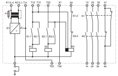
PILZ.jpg

The documentation says:
When the operating voltage is supplied,
X1 - X2 and T33 - T34 are bridged and the input circuit is closed, relay K3 energises.
• Input circuit closed (e.g. Emergency Stop
Button not activated): Relays K1 and K2 energise via the N/O K3.1 and K3.2 and latch via K1.1/K2.1. The status indicators illuminate. The safety contacts (13-14/23- 24/33-34) are closed, the signal contact (41-42) is opened.
• Input circuit opened (e.g. Emergency Stop Button activated): K1 and K2 de-energise. The safety contacts (13-14/23-24/33-34) are opened redundantly, the signal contact (41-42) is closed.
Which is somewhat less than crystal clear. What energizes K3? shorting T11 and T12 (or T11 and T22)? And then if X2 has 24V it will stay energized? Or does it require 24V on X2 to energize K3?

What do they mean by "X1 - X2 and T33 - T34 are bridged"? By wire? By an E-Stop button? X1, T33, and T34 are Not Connected in my circuit, it looks like those are a reset function.

In my circuit, there is a short loop through the E-Stop buttons and a couple of relay contacts which would short T11 to T12 (which is bridged to T22). A much longer series of contacts from T11 to X2 which any number of conditions would break. The symbol used for the K3 coil is very confusing to me - the black box at the end connecting to T12 and T22 seems to be the key - how does that work?

I think the problem is that the 22 relays in the cabinet are suspect, all 20 years old and somewhat contaminated by coolant mist. When I measure the resistance across contacts, I find some can be very flakey. I am considering replacing the lot of them, costs about $2000, but without pinpointing the problem I may just be flushing $2000 for nothing - they need replacing, but if I can't otherwise fix the machine then a waste.
 
For laughs, this is the circuit in the machine. My main question is what does the T12 input do, and what does the X2 input do. From this I would guess that X2 must be high to get the relay energized, it will latch on provided T12 is high until T12 goes low (E-stop - I think K18 and K19 would be closed in normal operation, K170 would be open). What is puzzling is the Enable 24V momentary button directly controls K170 so it would make T12 but break X2. That suggests that T12 initiates, what does X2 do? The X2 loop goes off page to A1.1/X70 ( a relay in the drive) and to A172 (an expansion for A170 qualified by a few other contacts).

PILZWired.jpg
 
I’ve had issues with Pilz modules in the past. If they get left idle for any time, the switches can fog up. I have had success by noting the positions of switches on the modules then rotating them a few times before returning them to their original positions. Take pics before to ensure the original conditions are maintained.
 
Only one of the PILZ relays has a rotary switch, and it is not likely to be involved (in the tool change circuit). I can try your suggestion on that one. I'm almost to the point of understanding the convoluted relay logic, but the operation of the PILZ E-Stop relays is still obscure. I'm not sure wrote the documentation for them, but clearly not a professional tech writer.
 
I started having problems with my 2000 DMU50V Millplus control related to the safety chain. I replaced a few of the cabinet relays that had high resistance contacts, and some of the e-chain relays on the servo control boards. That helped a bit but still was getting errors that froze the machine. Solution was to replace the CPU cabinet power supply. (It went completely dead so I had to anyway). That power supply provides the 24VDC for the E-chain on the Millplus PG1220 control.
When I was limping along, I also got into the habit of snapping the cabinet relays before powering up. That seemed to help a bit. I looked at the PILZ relay wiring but never touched them, just prayed that it wasn't them!
 
  • Like
Reactions: Ox
For laughs, this is the circuit in the machine. My main question is what does the T12 input do, and what does the X2 input do. From this I would guess that X2 must be high to get the relay energized, it will latch on provided T12 is high until T12 goes low (E-stop - I think K18 and K19 would be closed in normal operation, K170 would be open). What is puzzling is the Enable 24V momentary button directly controls K170 so it would make T12 but break X2. That suggests that T12 initiates, what does X2 do? The X2 loop goes off page to A1.1/X70 ( a relay in the drive) and to A172 (an expansion for A170 qualified by a few other contacts).

View attachment 382844
Hello,

Looks like safety relay is set to work in single channel input mode as there is a bridge between T12 and T22. Means that loop starting from T11 ending to T12 must be closed before output contacts (13-14, 23-24, 33-34 and 41-42) can be energized. And output contacts are energized after there has been pulse (+24V) at terminal X2.
 
To test the PNOZ Relais, make a bridge between T11 and T12. After making the bridge, make temporary bridge between T11 and X2.
PNOZ should be energized now... if you remove bridge T11 / T12 relais shoulkd be deenergized...

Regards
Patrick
(first post, will write introduction later)...
 
Hello,

Looks like safety relay is set to work in single channel input mode as there is a bridge between T12 and T22. Means that loop starting from T11 ending to T12 must be closed before output contacts (13-14, 23-24, 33-34 and 41-42) can be energized. And output contacts are energized after there has been pulse (+24V) at terminal X2.
That is my guess as to how they work. In this case, X2 is at 24V when that whole chain of relay contacts is complete, which represents the machine at rest prior to enabling the drives. A pulse is provided to T12/T22 by K170, which turns it on and latches it on, as multiple relays in the X2 chain open. The T12/T22 input stays high as K18 and K19 close. It stays this way until either one of the E-Stop buttons is pushed, or K18 or K19 open.

That is what happens. The missing piece is the action of the K3 relay coil/logic. It is represented in PILZ documents as a open box energized by the X2 terminal, but with a black box on the left with inputs from T12 and T22. From observing operation, it appears that to get the K3 coil actually energized, you need 24V at X2, and also a 24V pulse (or continuously?) at T12 OR T22. Is that correct?

This would have been very easy for PILZ to explain in their literature, not sure what they are trying to hide or perhaps the English translation is just bad.
 
I started having problems with my 2000 DMU50V Millplus control related to the safety chain. I replaced a few of the cabinet relays that had high resistance contacts, and some of the e-chain relays on the servo control boards. That helped a bit but still was getting errors that froze the machine. Solution was to replace the CPU cabinet power supply. (It went completely dead so I had to anyway). That power supply provides the 24VDC for the E-chain on the Millplus PG1220 control.
When I was limping along, I also got into the habit of snapping the cabinet relays before powering up. That seemed to help a bit. I looked at the PILZ relay wiring but never touched them, just prayed that it wasn't them!
Power supply seems good. Some of the cabinet relays have suspect contacts, many of them are redundant (two in parallel). When I check the voltage though, everything seems to be as it is supposed to be. I've been able to get the 24V enabled which turns on the PILZ relays, the control gets to the point of wanting to home, but will go no further. Like it is waiting for something.
 
Power supply seems good. Some of the cabinet relays have suspect contacts, many of them are redundant (two in parallel). When I check the voltage though, everything seems to be as it is supposed to be. I've been able to get the 24V enabled which turns on the PILZ relays, the control gets to the point of wanting to home, but will go no further. Like it is waiting for something.
is there any chance the doors aren't "closed" as seen by the plc or tool changer in full return position?
also had a lathe that would sit and if I bumped the spindle it came to life. it was a looking for an encoder position and was a hair from getting there
 
No, the door is seen to close by both its associated PILZ relay and the PLC. The control has an input table which displays the actually observed input states. It also behaves quite differently with the door closed vs open, this difference is explainable by the other observed issues. Certain outputs are not getting set by the control, including the one to bypass the door safety logic. My assumption is that something in the power up or relay logic is causing this, but it isn't easy to understand. The PLC code is complex and there is no documentation for it at all. I may have to reverse engineer it to discover the cause.
 
We have a Pilz unit on a transfer machine, and my EE guy is not overly enamored with it in any way.
If he feels like taking the challenge on, he would like to look into deleting it.

Then I saw a Pilz booth at either the AUTOMATE or IMTS shows this last year.
I walked past - fast like ....


---------------------

Think Snow Eh!
Ox
 
PILZ isn't the only one making these safety relays. Omron, Bradley, a few others. They all seem very complex, made to be "fail safe" doing self testing and guarding against welded contacts and redundant contacts. I think in Europe there are requirements for this. The best explanations of function have been from Omron, but still very substandard. If you documented any other part like this you'd never sell any. But if required by law you sell a lot.
 
  • Like
Reactions: Ox
Yes here in Europe there ist the "Maschinenrichtlinie" and other standards where such devices are required... Found the fault?
If you like, i can have a look at the wiring diagrams (i'm from Switzerland, so i will now the german notifications...).

Patrick
 
The schematic for one device is posted above. The schematic for the whole cabinet is spread across about 40 pages. I could understand the others if I could understand the one posted. I think it is as I said in post #8.
 
It turns out, nothing at all wrong with the relays. The control RAM had uninitialized variables in it causing all the misbehavior. I won't comment on how stupid an elementary programming error that is on the part of the machine builder, but I've already seen stupid issues in the PLC programming so not a big surprise. Once RAM was cleared through an obscure procedure not described in any literature, machine behaves normally!


Back
Top