What's new
What's new

Pivot point test on dovetail?

Gard

Aluminum
Joined
Mar 18, 2016
Working on saddle and cross slide of SB 10L lathe. It's getting a lot better but is still tighter at the ends of travel than in the center when I assemble it for a test fit.
I have used the Kingway type tool, Foster angled straitedge and various indicator setups on the surface plate. I think part of the problem may be a slightly convex or concave surface someplace. I found I can pivot the cross slide by hanging it off a blued angled straitedge that is held in a vise at a slight angle. I rescraped the part to improve the pattern and get the pivot points closer to the 1/3 points.
KIMG1307.JPG
Next I move on to the saddle again. I built a tilting table to hold the saddle while scrapeing and to balance the straitedge. This works OK but I cannot do a pivot test because all the weight of the dovetail is pressing into the corner. I can get a reasonable blueing pattern but not sure i trust it.
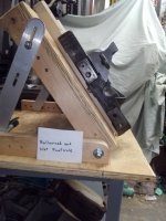
KIMG1309.JPG
Next thing I tried was to put the saddle back on on horizontal surface and I added a counter weight to the straightedge. I clamped a dial indicator clamp to the straitedge then added a vise to that as a counterweight. Then I adjusted the vise position so the entire contraption balances on the saddle. This showed me the pivot points were at one end and the middle so I have a little touch up to do. I think I will make a heavier duty clamp for the counterweight. KIMG1310.JPG KIMG1311.JPG
I am not sure how to best check flatness of the angled surfaces of the saddle. I may try to put the tilting table on the surface plate and adjust the angled surface level so it can be checked with an indicator. I know I need to check the actual angle against the cross slide and need to check spacing on the saddle with the kingway type tool. I also need to check cross slide with gib attached with the Kingway. I have checked alignment on the surface plate to an arbor that replaces the lead screw on the saddle. I found that using a dial indicator on the surface plate seems to work better on a blued surface so I do not waste time investigating scrape marks or areas areas that are too low. I have relieved the vertex of the dovetails with a hacksaw blade. I think I just need to keep going back and forth between these various checks, it does seem to be getting a little better with each iteration. My hat is off to anyone that could make a living doing this kind of work, I have a lot to learn.
 
I sure wish you could take a class, I should show you a simple way to do this. You must have a high degree in some profession as you have over thought this simple test.
Do you have a Connelly Book - Machine Tool Reconditioning? If you don't I sell them on Ebay and I can sell them to you direct and give you a PM deal. Just message me. If you have one look at page 59 and at the bottom of fig. 9.10 you can see how you should open the bottom of the angle. I use a hack saw or rpm electric grinder with a thin cut off wheel. Or if you have a shaper or mill use a cut-off wheel. Also Chapter 17 starting on page 129 helps too.

It I were you I would buy some Dura Bar from Speedy Metals or from Dura-Bar. and saw a triangle. Or cut the Foster SE. Mill it narrow so it will fit in the dovetail. Clamp the compound in a table vise or a Kurt Vise. Your compound looks like it's about 4 or 5 " long? The SE could be 6 to 8" long.

One thing many neglect when testing geometry is the machines in our shop. If you have a milling machine and you indicate your vise jaws in to .0002; in 8" you can indicate in your compound or if you have a surface grinder use it to act as a parallel tester. I have a ton of pictures I can find and attach. I will look now and later, I am tired as I just took a pain pill. I had surgery last Friday....have a little pain. Hmmm what happened to the pictures I had stored on here? You could cut the Foster SE just to the left of the eyebolt as it is to high to get a good grip to blue it up good. Or make on from some Dura-Bar.
 
Last edited:
Richard, thanks for the reply. You are correct, mechanical engineer in semiconductor fab for many years, not the first time I have heard the comment about overthinking things LOL. I do have the Connelly book, have read it several times and will again. My adjustable angle table was inspired by his "turn table" figure 4.2 on pg 13. I used a hacksaw blade to open up the bottom as you suggest, I can see where the cutoff wheel on the angle grinder would make quick work of that job.
The Foster straitedge will fit into all the surfaces it needs to but I did not appreciate how tricky it is to use it to mark a dovetail surface that is only 1/2 inch wide. It is the (7" long) cross slide fit to the saddle I am working on now. I think you are correct, a smaller triangle SE would help. I remember you mentioning using the milling machine last year when I was working on the compound dovetail so I put the cross slide on the mill and spent a lot of time cranking the table back and forth trying (and failing) to get it dialed in, not sure what I was doing wrong there.
Clamping the SE in a vise and hanging the cross slide off of it seemed to work pretty well for getting stable readings, key being that the center of gravity of the cross slide needs to be directly below the surface that is being marked as in my first photo.
Best wishes, I hope you heal quickly.
 
Not to over think things ;-) I took my Foster SE that’s the same as OP’s, clamped a similar sized weight cantilevered off it’s middle and hinged it. Not flat anymore.. Suspect the OP is getting false rubs. One more reason to use a smaller SE?

I do enjoy using Denis’ SE, just wouldn’t use it this way.

L7
 
Just to be clear, do you think the counterweight has caused your straitedge to warp? If so, did it come back after removing the weight?
How many different straight edges does a guy need? LOL
 
How many different straight edges does a guy need? LOL
Guilty as charged! ;-) Only have two of Denis’ nice straight edges. Would have three if he’d made one like his 48” only longer. (Hint)

Yup, it hinged normally after weight removed. I might be unnecessarily anal, but try to put minimum even presure on SE when printing.
 
Test i and see if it bends. Lucky brought one to the Rockford class he attended a few years ago and we tested it on a granite straight edge and it bent to he weight of his hands. It was a 36" if I remember right. ALL prism straight-edges bend to some extent, no matter how well they are designed. A camelback is better then a prism SE. That's why I make a 12" my HKA-12 camelback SE with 2 angles on it. a 45 deg. and a 50 deg. I have also used a 18"or my HKA-18 camelback the way you do it. Putting it in a vise and rubbing the dovetail of a compound on the flat. To prove the stability as Lucky suggests. Use 2 steel 1 2 3 blocks like the Planokator shown in another thread and put a .0001" or .00005" indicator on the SE in the middle and press down on it and see if it bends. You could also wear a glove to avoid any chances of heat changing things. If Lucky says his bends, then it probably does as he is an experienced scraper. I trust his opinion. When scraping the compound you need to check both-sides of the compound to be sure they are not low or high in the middle. Does the slides have a taper gib or straight gib? If it is a taper gib you need to check the surface wear the gib rests against too as it gets high in the middle on 5 out of 6 compounds. I tried to attach picture I had stored on PM but I can't find them. I pray they have not been lost. I am going to email Charles and ask him to find a way to recover them. I have a 1 x 1 1/2 prism straight edge that I have that would work good I made it from piece of Dura-Bar. I will try to find pictures on my computer and attach them.
 
Working on saddle and cross slide of SB 10L lathe. It's getting a lot better but is still tighter at the ends of travel than in the center when I assemble it for a test fit.
I have used the Kingway type tool, Foster angled straitedge and various indicator setups on the surface plate. I think part of the problem may be a slightly convex or concave surface someplace. I found I can pivot the cross slide by hanging it off a blued angled straitedge that is held in a vise at a slight angle. I rescraped the part to improve the pattern and get the pivot points closer to the 1/3 points.
View attachment 365297
Next I move on to the saddle again. I built a tilting table to hold the saddle while scrapeing and to balance the straitedge. This works OK but I cannot do a pivot test because all the weight of the dovetail is pressing into the corner. I can get a reasonable blueing pattern but not sure i trust it.
View attachment 365298
Next thing I tried was to put the saddle back on on horizontal surface and I added a counter weight to the straightedge. I clamped a dial indicator clamp to the straitedge then added a vise to that as a counterweight. Then I adjusted the vise position so the entire contraption balances on the saddle. This showed me the pivot points were at one end and the middle so I have a little touch up to do. I think I will make a heavier duty clamp for the counterweight. View attachment 365299 View attachment 365300
I am not sure how to best check flatness of the angled surfaces of the saddle. I may try to put the tilting table on the surface plate and adjust the angled surface level so it can be checked with an indicator. I know I need to check the actual angle against the cross slide and need to check spacing on the saddle with the kingway type tool. I also need to check cross slide with gib attached with the Kingway. I have checked alignment on the surface plate to an arbor that replaces the lead screw on the saddle. I found that using a dial indicator on the surface plate seems to work better on a blued surface so I do not waste time investigating scrape marks or areas areas that are too low. I have relieved the vertex of the dovetails with a hacksaw blade. I think I just need to keep going back and forth between these various checks, it does seem to be getting a little better with each iteration. My hat is off to anyone that could make a living doing this kind of work, I have a lot to learn.

Working on saddle and cross slide of SB 10L lathe. It's getting a lot better but is still tighter at the ends of travel than in the center when I assemble it for a test fit.
I have used the Kingway type tool, Foster angled straitedge and various indicator setups on the surface plate. I think part of the problem may be a slightly convex or concave surface someplace. I found I can pivot the cross slide by hanging it off a blued angled straitedge that is held in a vise at a slight angle. I rescraped the part to improve the pattern and get the pivot points closer to the 1/3 points.
View attachment 365297
Next I move on to the saddle again. I built a tilting table to hold the saddle while scrapeing and to balance the straitedge. This works OK but I cannot do a pivot test because all the weight of the dovetail is pressing into the corner. I can get a reasonable blueing pattern but not sure i trust it.
View attachment 365298
Next thing I tried was to put the saddle back on on horizontal surface and I added a counter weight to the straightedge. I clamped a dial indicator clamp to the straitedge then added a vise to that as a counterweight. Then I adjusted the vise position so the entire contraption balances on the saddle. This showed me the pivot points were at one end and the middle so I have a little touch up to do. I think I will make a heavier duty clamp for the counterweight. View attachment 365299 View attachment 365300
I am not sure how to best check flatness of the angled surfaces of the saddle. I may try to put the tilting table on the surface plate and adjust the angled surface level so it can be checked with an indicator. I know I need to check the actual angle against the cross slide and need to check spacing on the saddle with the kingway type tool. I also need to check cross slide with gib attached with the Kingway. I have checked alignment on the surface plate to an arbor that replaces the lead screw on the saddle. I found that using a dial indicator on the surface plate seems to work better on a blued surface so I do not waste time investigating scrape marks or areas areas that are too low. I have relieved the vertex of the dovetails with a hacksaw blade. I think I just need to keep going back and forth between these various checks, it does seem to be getting a little better with each iteration. My hat is off to anyone that could make a living doing this kind of work, I have a lot to learn.
I would mount the SE in a vice or wood Johansson clamp or a wood devise to hold the SE vertically and rub the compound slide to it. It will be awkward but I would pivot or hinge it at 30 %. One side at a time. I tried to download some pictures from my computer like I used too on the old PM but it says my files are to large. I'll try to lower the size and try again. I also wrote Charles.
 
Working on saddle and cross slide of SB 10L lathe. It's getting a lot better but is still tighter at the ends of travel than in the center when I assemble it for a test fit.
I have used the Kingway type tool, Foster angled straitedge and various indicator setups on the surface plate. I think part of the problem may be a slightly convex or concave surface someplace. I found I can pivot the cross slide by hanging it off a blued angled straitedge that is held in a vise at a slight angle. I rescraped the part to improve the pattern and get the pivot points closer to the 1/3 points.
View attachment 365297
Next I move on to the saddle again. I built a tilting table to hold the saddle while scrapeing and to balance the straitedge. This works OK but I cannot do a pivot test because all the weight of the dovetail is pressing into the corner. I can get a reasonable blueing pattern but not sure i trust it.
View attachment 365298
Next thing I tried was to put the saddle back on on horizontal surface and I added a counter weight to the straightedge. I clamped a dial indicator clamp to the straitedge then added a vise to that as a counterweight. Then I adjusted the vise position so the entire contraption balances on the saddle. This showed me the pivot points were at one end and the middle so I have a little touch up to do. I think I will make a heavier duty clamp for the counterweight. View attachment 365299 View attachment 365300
I am not sure how to best check flatness of the angled surfaces of the saddle. I may try to put the tilting table on the surface plate and adjust the angled surface level so it can be checked with an indicator. I know I need to check the actual angle against the cross slide and need to check spacing on the saddle with the kingway type tool. I also need to check cross slide with gib attached with the Kingway. I have checked alignment on the surface plate to an arbor that replaces the lead screw on the saddle. I found that using a dial indicator on the surface plate seems to work better on a blued surface so I do not waste time investigating scrape marks or areas areas that are too low. I have relieved the vertex of the dovetails with a hacksaw blade. I think I just need to keep going back and forth between these various checks, it does seem to be getting a little better with each iteration. My hat is off to anyone that could make a living doing this kind of work, I have a lot to learn.
On the top photo you say the SE is not pivotal. Yes it is. Lift the SE up about 1/8" to 1/4" vertically. take it off the bottom or vertex of the slide and holding the SE from both ends and practice pivoting it. It will take some practice. A smaller and shorter prism SE made from a piece of Dura-Bar would be easier to hold. Or come to the MN scraping class and I'll show you how. It's really easy. I have room in the July class. I will try to organize a October and November class too.
 
Working on saddle and cross slide of SB 10L lathe. It's getting a lot better but is still tighter at the ends of travel than in the center when I assemble it for a test fit.
I have used the Kingway type tool, Foster angled straitedge and various indicator setups on the surface plate. I think part of the problem may be a slightly convex or concave surface someplace. I found I can pivot the cross slide by hanging it off a blued angled straitedge that is held in a vise at a slight angle. I rescraped the part to improve the pattern and get the pivot points closer to the 1/3 points.
View attachment 365297


You need one of my 8" prism/parallels. ;-)
Comparing the approximate dimensions of the 18 to the casting you are working on I would guess that the distance between the doves is about 2." As cast, my 8 is 1.875 on the sole and so after machining would fit in there nicely. It would also be a convenient to work with on a part that size.

I am sure it would bend if subjected to a load. Only Kryptonite won't bend when loaded. ;-)

Denis


As people much smarter than me keep telling me, everything is a noodle, and everything bends. The key is to figure out how to minimize and if you can’t, then quantify.

I frequently use Denis’ 18” prism and like it. I just try to use every straight edge in a ’relaxed’ state.
 
In some of these situations it's a little like developing "feel" when you're reading micrometers to tenths and trying to get reliable and repeatable numbers. To gain confidence with mics one could find a gauge pin that you know the correct size to very close limits, then practice holding and tightening the mic until you get identical, consistent readings. Then you know your mic and how to jiggle or twist or whatever to get good results.

The parallel process with dovetails and prisms or straightedges is to hold carefully, balance, pivot and "feel" where the parts want to pivot themselves. A step in that might be to deliberately scrape the center just a little low so you know it's going to touch and pivot at the ends. Then explore how if feels to find that pivot sense out at those places. Then when you're checking an unknown surface you'll have a better feel for what you're looking for. The parts don't always have to be perfectly balance like you were trying to do so long as you can support the parts without too much fatigue or so much weight you can't sense what's going on. Put your awareness, if you will, right in the contact area of the parts and explore that space.

Years back I ran the jig grinder and one of the jobs was to grind the ID of steel rings for an interference fit with carbide inserts. No air gauges, we did it with telescoping gauges and the previous guy taught me how to do it. It took careful feel but it worked. Fast forward and I changed jobs but they told me about the guy who followed me on the machine. The first time he did it he ground the rings, put them in the over for the required time, took them out and dropped the blanks into them and let them cool. When cold he picked the rings up and the blanks fell right out. That's the benefit of "feel".
 
Little topic stray, but curious about telescopic gauges. I mostly use the double ended Starretts but have two of the larger older Moore and Wright single end gauges. The M&W seem easier to get consistent results. Is this expected? if yes, why aren’t they more common?
 
It would be helpful to see it done in person but I am sure I will eventually get it done good enough for who its for... I am afraid I do not understand what you are saying. When I am scrapeing a flat surface like a SE with it resting directly on the surface plate, I push sideways on one corner with a single finger and and look for what point it pivots about, it should be 1/3 of the way from the far side. At least this is my understanding. If the surface being marked is vertical, and I am supporting the SE weight at each end won't the pivoting point be dependent on how hard I am lifting on each side? I move the SE back and forth a little and get a pattern. I am a little concerned that the pattern might be dependent on how much pressure I am applying where.


Its tempting to put some lapping abrasive in the assembled slide and work it back and forth but I don't think that is the correct play.
 
As TC Tool said it takes practice. You need to be patient. Don't screw it up using a lapping compound. I hinge my parts or SE's by holding each end with my hand and moving my hand as a unit. I hate to see rookies use the one-finger push. When I see that I know the person has little experience and is self-taught.
 
Thanks for the links to the videos, that helps. That is the same way I have been doing hinging for flat surfaces resting on a surface plate, I just did not describe it very well. I was able to do a similar hinge the inside dovetail surface of the cross slide by hanging it from the SE as in the my first photo.
I must admit I had not really considered that my techniques might be warping the SE, I suspect the SE is still more flat than the part I am scrapeing but I will do some more measurements to verify, thanks for pointing it out.
I can see where a smaller triangular SE would balance better in the small dovetail. However, because of the shorter height it will also be less rigid than the Foster. I will have to put one on the wish list.
I can see there is some feel and skill involved in marking the dovetail with a SE, I guess in the end I will be able to confirm the 4 surfaces are flat when I check the dovetail width, either with dowels or the Kingway type tool.

I still need to refine the fit of the tapered jib on the cross slide. I found this last step to be a critical one when scrapeing the compound rest last year.
 
I have decided to buy some Dura-Bar and for a test I will make and (mill and scrape) send to you make one for you to do a comparison test. You can decide which one works the best. It seems as if this new picture format has lost all my old photo's on here and when I can get out to the shop next week, I'll take some photo's and post them here. I also have a cool rotating vise devise I have photo's of that CCI has in Idaho where I taught a class 3 weeks ago. Also have pictures of a wood holder that Tom Utley made to hold prism Straight-edges at a Keith Rucker Class I taught a few years ago..


Back
Top