What's new
What's new

Plan for aligning head and tail on SB 10L

Gard

Aluminum
Joined
Mar 18, 2016
The bed has been planed and scraped, Rulon added to the saddle. Now onto scraping and aligning the headstock and tailstock. The lathe came with collets and some chucks so I first tried to mount a 7" test bar and also a center in a collet. The lathe failed tests for runout. I did not know if the problem was the spindle taper or the collet system so I decided to build a test bar on another lathe. I got the taper machined to a good match to the spindle and then flipped the bar between centers to machine the strait section. This needed some filing to get diameter within about +/- 0.0001". When installed in the 10L spindle I still got +/- 0.0016 runout at the end. I removed the test bar, rotated it 90 degrees, and reinserted it. The high spot stayed at the same point on the test bar. As this was repeated, the high spot always followed the test bar instead of the spindle. I am convinced this means the problem is in the test bar and not the spindle internal taper. I guess I have some learning to do on the art of turning parts between centers.

For now I have marked a line down each side of the test bar that is at the mean of the maximum and minimum reading when rotating the spindle with the test bar. These lines are where all measurements will be done. My plan is to not install the bearing caps until the head is scraped into alignment with the bed? I can carry the bare head easily, if it was assembled I would need to use a hoist. I have a purchased test bar for the tailstock MT2 spindle. The photo shows both test bars installed in the lathe, they seem to be too long for a machine of this size, are there any guidelines for test bar length? Machine tool rebuilding makes note at one point that it should be related to lathe size but then lists specs only for a 12 inch bar. If there is a recommendation on test bar length for a 10" swing lathe, is it based on total bar length including the taper or just the length of the strait section?
KIMG1614.jpg
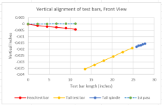
I did some initial scrapeing on the 3 parts to get reasonable contact and improve alignment. (bottom of headstock and the tailstock top and bottom). Next I decided to map out the current state of the parts so I installed both test bars, mounted a dial gauge to the saddle cross slide and ran down the top of both test bars. At each measurement point I subtracted off 1/2 of the diameter of the test bar. The headstock center is about 0.015" higher than the tailstock, this seems like a lot of material to remove from the headstock with a hand scraper. Both the head and tail test bars point down by what seems a lot to me so I need to step scrape the outside of both to get the test bars horizontal or slightly pointing up.
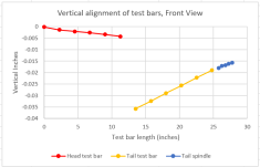
1676036162791.png
I also measured the horizontal alignment by running the dial indicator down the front of both test bars. This is much better than the vertical. The ends of the test bars pointed slightly away from the front of the lathe and they need to be either parallel or tip slightly towards the front. You can also see that the test bar does not align perfectly with the tail stock spindle, I will have to check for repeatability of this. I think it is more important for the test bar to be pointing in the correct direction than the spindle outside diameter?
1676036395479.png

I realize I could probably improve alignment by stiffing shims of various thicknesses under the headstock and between the two halves of the tailstock. However I would like to rebuild it using as few shims as possible. Here is what I am thinking of doing.
1) Finish scrape in the bottom of the headstock to get the test bar pointing in the right direction in horizontal and vertical.
2) Roughly scrap the bottom of the tailstock to get its test bar parallel in the horizontal and vertical plane
3) Add rulon and glue to bottom of tailstock
4) Use a 4 jaw chuck on the headstock spindle to tweak the test bar alignment, add a small clamping force.
5) After cure make note of height difference between the now hopefully parallel test bars.
6) Move the bottom of the tailstock to the milling machine and machine the rulon strait down to within about 0.002" of its final
7) Finish scrape the rulon for alignment of the test bars.

I know this bypasses some steps in the rebuilding book but I guess I don't see the need to scrape the two halves of the tailstock into alignment to the lathe as long as they fit each other and the test bar is pointing in the right direction. One issue is the tailstock spindle only extends 2" and its surface shows some wear so it does not seem to be as reliable of a reference surface as the test bar.

I have also considered putting Rulon on the bottom of the headstock, mostly because it is so much easier to scrape than cast iron.

Open to suggestions
 
For now I have marked a line down each side of the test bar that is at the mean of the maximum and minimum reading when rotating the spindle with the test bar. These lines are where all measurements will be done.
I have not had good result with marking the measurement points on test bars. I think the high, low, and average spots really need to be remeasured every time. Yeah it takes forever.

2) Roughly scrap the bottom of the tailstock to get its test bar parallel in the horizontal and vertical plane
Better to align the quill than the test bar mounted in the taper.

3) Add rulon and glue to bottom of tailstock
Add it to the bottom of the main casting, or the top of the base, not the bottom of the base.

5) After cure make note of height difference between the now hopefully parallel test bars.
For measuring height differences, it's more accurate IMO to put dead centers in the spindle/quill and run a straight test bar between them. Align them horizontally before you take the vertical measurement.

One issue is the tailstock spindle only extends 2" and its surface shows some wear so it does not seem to be as reliable of a reference surface as the test bar.
Don't you want to address that wear before going through all this work? The tapers can be surprisingly inaccurate.
 
I have not had good result with marking the measurement points on test bars. I think the high, low, and average spots really need to be remeasured every time. Yeah it takes forever.


Better to align the quill than the test bar mounted in the taper.


Add it to the bottom of the main casting, or the top of the base, not the bottom of the base.


For measuring height differences, it's more accurate IMO to put dead centers in the spindle/quill and run a straight test bar between them. Align them horizontally before you take the vertical measurement.


Don't you want to address that wear before going through all this work? The tapers can be surprisingly inaccurate.
Thanks for the suggestions
I did not mention I installed the homemade test bar in the spindle and have not removed it for the duration, I just pick the spindle-test bar assembly off the head stock and set it on a padded work bench. I have checked a couple times and the mean always falls on my marked line. I will keep checking.

Is there some reason Rulon would not work as well as a bearing surface on bottom of the tail stock base? The bottom surface inverted V needs to be scraped for alignment in any case.

I understand putting a test bar between centers but I don't currently have an accurate dead centers for either for the headstock or tailstock. The tailstock live center has some play in it. Perhaps I will make or buy some new centers at some point.

My initial thought is there is probably some wear on the tailstock spindle as well as the bore it fits into. Perhaps I will dig into that a little more. Alignment does change a little depending on how far the quill is extended, mostly in the horizontal plane but I think there is a work around by adjusting offset. I have not found a good way to fix a taper that is not coplanar without reboring and there is not much extra meat for that.
 
For the tailstock base, you probably don't want Rulon because the tailstock might not clamp as solidly (the Rulon being pretty slippery). You're better off leaving metal-to-metal on the bottom of the tailstock, and shimming the height between the tailstock base and upper section, probably, where you could use various types of shim material of any thickness required.
 
I may be missing something here but are you trying to do any kind of alignment without the bearings shells in place and with the correct clearances set? I would not remove any metal from anywhere until that step is performed.
 
Good point about slipperiness of the rulon, I had not thought about that. I guess I could scrape in the bottom V to get horizontal alignment perfect and then add rulon and machine it to tweak in the vertical alignment to be at the correct height and pointing up slightly.

Jim, good point but this is an older SB with the integral segmented cast iron bearings, there is no removable bearing shell like the newer machines. So the head stock spindle is sitting directly on the clean lightly oiled bottom bearing surface. I have not yet fit the bearing cap. There is provision for changing shims under the bearing cap but I do not think that will change alignment. It makes it convenient to lift off the spindle, flip over the headstock, set on the workbench and start scraping. This lathe lived in Wappingers Falls NY, relatively unused for about the last 25 years until we cleaned out my Dads house.

I can understand wear on the tailstock but is it curious that the headstock is this far out of alignment?
 
Tailstocks always go low. The standard bodge of course is shim between the sections after the underside of the bottom is scraped to fix the droop. Another way is to simply fabricate a new taller base.

The 4 thou of droop at 10 inch extension - cannot fathom that. I doubt you took off hardly any when you scraped for bearing. You would have to machine that much off to get close. To double check this see how much shim it would take to get the spindle axis parallel to the ways. You have bolted the H/S down and double checked this? Possible you have some rocker action going on by mistake? I would put the tailstock on hold until you sort that out.

Collet adapters in those lathes wear tri-lobed if they are high mileage. That can give odd results for runout for parts held in the collet. Put a dial gage inside the coolet adapter and see what you've got. They can 'grow' ridges almost 0.001 tall.
 
Jim is right. Install the spindle like your going to use it when it's done. Don't try to reinvent the wheel. I have some suggestions, but I'm, pooped. Long week teaching a class in PA. You also need shorter test bars and the same diameter. Spliting the difference on the test bar is OK it your talking about .001" or less. How is the TS qull? tight in the bore? Gard your a sharp guy but your complicating a simple job. You should have asked us for help before posting that mess. You can buy cheap but good spindle test (taper) bars off ebay that are made in India. If not there are some simple ways to do this. Just ask Jim, Jerry, Matt, me - the experienced rebuilders on here, for help!
 
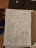
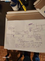
You say you have another lathe? Micrometer the OD of the TS quill, then on your other lathe turn down a piece of aluminum 2" diameter and make 2 collars the same size in it 3/4" from the chuck undercut it. I am going to draw a sketch and take a photo and post that. Do much easier then trying to type it...BBL Im in my hotel room and drew it on a postal envelope. Oh I would use a 8 to 10 inch shaft and make the 2 collars 6" center to center so you can use 12" as your spec. or divided by 2...

You have to install the headstock spindle first. This method has been successful for my entire career.. The 2 collars can be used to indicate in the head stock from the lathe bed. The same size of quill on the end of the aluminum shaft isto align the height of the tail stock. If you haven't down anything to the lathe bed and headstock you could turn the shaft down in that lathe.

Gard your so good at cad cam and drawing - how about re-drawing the sketch once you have done it.. I have errands to do...BBL. Rich

PS. Have it posted horizontal then vertical...hopefully you will forgive me for my crude sketch...
 

Attachments

  • 20230211_094206.jpg
    20230211_094206.jpg
    1.4 MB · Views: 23
  • 20230211_094339.jpg
    20230211_094339.jpg
    1.3 MB · Views: 23
Last edited:
Jim, thanks for the insight on the collets, it confirms what I thought I was seeing.

When you say "4 thou of droop at 10 inch extension", I assume you are talking about the headstock test bar. There is actually a little more to this story, When Rees Acheson was setting up the lathe bed on his planer last spring he was surprised to see that the area under the head stock was tipped up at the far end, I think he said about 0.006" relative to the other original surfaces. I was able to sort of confirm this by looking at the bottom of the bed in that area. We had some discussion about this and concluded perhaps the bed was bent near the head at some point in its life. Rees planed all the top bearing surfaces of the bed strait and only a little scraping was required by me. Anyway now I think someone scraped the bottom of the head into alignment with the rest of the bed. Now that the bed is strait, I have to go back the other way. I have no idea if it was shipped from the factory that way or or if it had an "event" and rebuild at some point. I started step scraping the head yesterday and already have it in much better alignment to the bed.

"The standard bodge of course is shim between the sections after the underside of the bottom is scraped to fix the droop" I will follow this advice and then see where I am at for height. Connolley says to scrape the head down to align to the tail, but I suspect I will end up with some sort of shim, hopefully glued in place.

Richard, The tail stock test bar is one I purchased from India. This one has a MT2 on one side and a MT3 on the other, perhaps I should of bought seperate shorter bars, one of each. Unfortunately the old SB 10L lathe has a custom headstock taper so no reasonably priced test bars are available which led me down the road of making one. It was made from a worn out pivot bolt from a logging grapple I rebuilt for a customer. It has a runout of +/- 0.0016" at the end and less as it gets closer to the headstock. I think I will need to continue using it as I am not sure how much better I could make it using the 1945 14 1/2" SB lathe. From what I have read making test bars is a job more appropriate to a grinder.

Is there any kind of rule of thumb for how long the straight section of a test bar should be for example relative to the swing of the lathe?

"How is the TS qull? tight in the bore?" The quill has only about +/- 0.0018" movement in horizontal and 0.0025" vertical with the quill clamp loose and about +/- 0.0001" with it clamped. I am in the habit of putting just a little force on the clamp when I am starting a hole with the tailstock or I use a lathe bit to steady the drill tip. I don't have a lot of experience to say how bad this tailstock is but it seems sort of in line with the couple of other machines I have used.

David
 
I can see the advantage of having test bars that are all exactly the same diameter as the quill, there are no calculations needed. However it is now pretty easy for me to measure the test bars like in my original post. The quill and test bar diameters and the equations are all in the spreadsheet and I have an indicator set up for vertical and another for horizontal alignment. I leave the headstock test bar installed in the spindle. The data from the test bars is needed anyway to ensure alignment to the lathe bed as I scrape the headstock and tailstock bases.
 
Gard. I am trying to make a historical thread as people will be reading this for years. You can see how people resurrec old threads on here and write in them. I want those readers to see how a PRO does it. You can take our advice or re-invent the wheel. I just want those other readers see how the pro's do or did it. I'm not trying to argue with you.
 
I am always very interested to see how the pros do it. Often I read the posts and have a DUH, why didn't I think of that moment. I apologize if anything I said came off as argumentative. I usually try to remember to point out that I am an amature in these matters. I always struggle trying to explain something, I keep going on and on until it seems like the other person understands what i did, not necessarily that they agree it is the right or best way.

The comment about re-inventing the wheel is spot on for me, I acquired 35 US patents over the years when I worked for IBM. One of their claims was having more patents than any other company so a lot of those patents never made it into a product but I got my little award each time anyway.
 
A friend of mine who has passed away worked at Honeywell Think Tank before he retired. His name Was Richard Visnor. A PHD in Mechanical Engineering. He had 17 patients in Optical alignment equipment. One of his inventions was a triangle glass part that had holes drilled in it and a laser beam went through it (explaining it above my pay level).used in a cruise missile guidance system. If you didn't know who he was, you would have never known. He drove an old beater Lincoln, wore lumber-jack shirts (red and black), lived in a crappy house. He bought an old church in the country with paint peeling and plastic over the windows. LOL.. I drove bye it 3 times trying to find his shop when I met him. When I went inside it was like a laboratory. He said he didn't want anyone knowing what he was doing inside there.. No one snooped around that place...lol

I suspect if he wrote on here he would be just like you...LOL

Rich
 
Another DR that I know, who was a old friend of my Dad and he is 91 and my Dad taught him to scrape, and just lost his wife of 65 years. Is Bill Volna. If you mention the Connelly Book to him, he scoffs at it. He has an amazing website about optical equipment. He also invented "stuff" and he worked at Honeywell. The helmets that helicopter pilots wear that show where your shooting and flying. He helped develop that. It's in his website. Click on Bills sandbox....really cool... He is another man who is a genius who you would never know...if someone didn't tell you. https://volnaengineering.com/
 
Interesting web site, Kinematic couplings are a subject of interest to me also, used a fair amount in the semiconductor industry.
 
Ah, so there's more under the covers here. If the parentage of the machine is uncertain, then who knows what's been done to the headstock. I personally would avoid shims under the headstock if it's been worked over before, to that extent. Ok to set it up that way to see what you're up against but the rigidity would be somewhat compromised if used permanently I think. 1) possibly a replacement headstock? 2) sounds crazy but re-machine and re-scrape the underside to agree with the spindle axis. This would be one of those 'takes a week to set up, and 10 minutes to take the cuts' sort of jobs. If you have, or have access to, a milling machine large enough to do the job, it's a real education.

I would re-install the spindle and do the checks on it again, see how much would have to be removed from the underside.

Until the headstock spindle is settled, put the tailstock in a box on the floor out of the way.
 
Here is a better book about testing machine tools. It is the book the majority of machine specs are based from.
Jim is correct the best way to test the spindle is to take the test cuts in the machine. You can make the test bar like I showed and eliminate the long test bars. Those things are saaggggggging and your getting false readings. I would not trust anything your getting.
http://totallyscrewedmachineshop.com/documents/Testing Machine Tools (Dr.Schlesinger).pdf
Look on page 32 and33. The double mandrel test is similar to the test I am showing, but shorter. They are long, but the machine is assembled and rigid compared to your dinky machine. My Dad showed me that quill test and I have been using it and teaching it to my students for 40 years successfully. You also know which way the quill is pointing when it is locked and unlocked. You should also check the bottom 1/2 or sole as it is worn low in the front. You're getting way ahead of yourself. Factories do the TS before the headstock. If you make the test bar in another lathe and put it in a 4 jaw chuck, dial it in then you don't have to run the machine. I would assemble the cross-feed screw so you and do the top dead center test while testing the bar and quill.
 
Richard, Interesting book, I am going to have to spend some more time with it. What I am doing for spindle alignment is the same thing shown in fig 59 pg 34. I have still not seen anything that mentions what the test bar length should be for a smaller lathe but it might be in there someplace? Sorry I have no cad skills, just data manipulation in a spreadsheet. I may be dense here but it is not clear to me how the 2 collars are functionally much different than 1 straight test bar. for checking spindle alignment to the lathe bed. I think having the lead screw installed would make alignment a little easier but I can find the top center of the arbor pretty easily by just sliding the cross slide manually. The mag base is mounted to the cross slide and contacts the test bar at either the front or top after rotating the test bar to the mean of the max and min reading.

Jim, In hindsight I fear I have confused things some by having one post covering both headstock and tailstock. As you suggest I am working on only the headstock now and have gotten it much closer by scraping the bottom (many cycles of er many hours). I have no intention of using shims between the headstock and lathe bed. This lathe is a long way away from making any test cuts, my goal is to get the head stock as close as I can given the limits of tooling I have or can make with the other lathe. Then assemble everything and try it out, probably months from now. I have taken the charts I showed in the first post and added dotted lines showing the current alignment for the headstock test bar in both horizontal and vertical. I have a little more work to do in the horizontal alignment, it should be pointing a little to the front.
1676208364141.png
For vertical alignment I think I am real close, I know it is OK for it to point up slightly but perhaps level is a better target considering the length and weight of the test bar?
1676208444056.png


Back
Top