What's new
What's new

Plan for aligning head and tail on SB 10L

I know I have a copy and the book and Connelly book inside my hotel room. Your still not doing it correctly as shown. That lathe is assembled. Your to anxious to do the tests. Assemble the spindle and do the tests again. Also assemble the apron and turn down a aluminum bar. If you insist you can use that long bar, but don't use that way to long tail stock bar and indicate the quill I would turn down a shaft the same OD of the quill and then indicate them. I have photo's in my computer showing this and will attach them later. You are a smart guy and have to see how non Engineering that set up your using is looks?.
 
If you’re worried about test bar sag you should measure it. Obtain a bar of the same diameter and the same length (without taper) and suspend it from the test bar using a bunch of rubber bands. We have to assume that the sag is linear — if the test bar sags X from its own weight, it will sag 2X from double that weight.

I did this experiment when I scraped my SB10L a couple years ago. My test bar is 12”, about 1-3/8” diameter. Measured sag was .0002”.
 

Attachments

  • 7C2A6C70-2090-406E-AA9A-B57ED5D1D43B.jpeg
    7C2A6C70-2090-406E-AA9A-B57ED5D1D43B.jpeg
    268.1 KB · Views: 12
Jwearing, that is an excellent idea, I just lifted up on the end of my test bar with a force of about 1/2 its weight and it moved up 0.0003", then I came upstairs and read your post. I think I like your idea better. What is the hole in the center of your bearing cap? Do you have the brass bearings?

Richard, I can certainty cut the tailstock test bar in 1/2, I guess in hindsight I should of bought seperate MT2 and MT3 test bars, then each would come with a center in each end. I could also cut down the headstock arbor. I went back and re-read chapter 15 of the Connelly book, it says test bars should always be hollow to reduce sag but was a little surprised no guidance given on recommended diameters or lengths. I will have to think about this some more. The pdf you provided does make it clear all accuracy measurements are per 12" of test bar length so actual test bar can be any length and measurement is calculated per ft of test bar

From a practical standpoint how do you do scraping on the bottom of a head stock? I guess a hoist is used to lift it off the bed, then it is flipped over onto some kind of blocking at a convenient height for scraping?

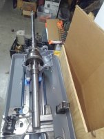
Following is some photos showing my 1.73" diameter test bar being measured. The head stock has cast iron bearing surfaces machined into the head casting, when I set the spindle in there it feels very solid, like using V blocks, there is no measurable play. I always add a counter weight to the left side of the spindle that off sets the weight of the test bar so there is roughly equal load on each bearing. The measurements will be repeated after the lathe is reassembled. I am certainty not trying to imply I am doing it the correct or best way, just wanted to make it more clear what I am doing and learn how the pros do it.
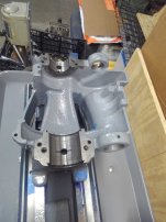
KIMG1620.jpg
KIMG1621.jpg
 
What is the hole in the center of your bearing cap? Do you have the brass bearings?
I have plain iron bearings as well. I think the previous owner drilled the hole to mount an indicator. IMO it’s fine to rough it with the caps off but they should be put on for the final passes.

the area under the head stock was tipped up at the far end, I think he said about 0.006" relative to the other original surfaces.

On my bed that area under the HS on the left was about .020" lower than the rest of the bed. I think SB wasn’t too worried about accuracy in that location, they just scraped the headstock to fit.

On test bar length: Richard has more experience than the rest of us so you should do what he says. I do like my test bars though and I think 12" is appropriate in the headstock. I think my MT2 test bar is only 10" long. IIRC the Schlesinger spec for tailstock alignment is quoted over only 4". That's because you should be aligning to the quill. The test bar is used later to ensure the taper is ground concentrically to the quill.

Here are a few shots of the same job on my Hendey: https://www.practicalmachinist.com/...l-gage-restoration.356424/page-7#post-4016334
 
Did you dismantle the tailstock? Did you check the bottom 1/2 on a surface plate? It will be or was low in the front as SB lathes your vintage did not have way wipers on the front of the TS sole. That needs to be scraped co-planer front to back side to side, before making those tests. The top of the sole should be original as it get only a little wear. Stone it and set the top upside down on parallels and test it. The outside clearance sides were milled or planned at the same time as the flat and V. You can use them to do your detective work. You can lay a dowel pin in the V front to back to figure it out. If it is more then a few thousands mill it before scraping it. After it is finished then do the test bar tests. If your measuring it before doing this, your putting the cart in front of the horse.
 
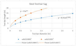
On the question of test bar lengths and diameters I realized I could get an approximate answer by calculating the deflection assuming the test bar is a fixed cantilever beam with uniform load (the weight). This is case 10 in machinery's handbook. I picked 0.0001" as an acceptable deflection. The equation simplifies to maximum length = 8.4 times square root of diameter. I also solved for a deflection 0f 0.001 as that would be way too high. Connelly says test bars should be hollow to reduce sag, I have no idea if this is done in practice today. It would be easy enough to add that curve to this chart if anyone is interested let me know. In reality, any deflection within the taper or spindle will be added to this calculated bar sag. I think this confirms my 1.7" diameter x 12" long test bar for the headstock is reasonable. My test bar for the tail stock is way to long, someplace around 5" or 6" would be reasonable. I will cut this one.

1676293472208.png
 
Richard,
In my original post I noted I have scraped the interface between the top and bottom, they now fit nice with good blueing transfer, the cross slide is tight. The bottom of the base was measured on the granite but there was not much original surfaces left on the bottom. A little ridge where the relief cut was made down the center of the V. I scraped in the bottom V and flat using the bed as a template (just so it would not rock on the bed during the clamping and measurement) than clamped the assembled tailstock on the bed and measured the quill (spindle). It was way out. I stuck my test bar in the taper and confirmed it is pointing in about the same direction. I have not decided if I will try to mill it to get close first. Seems like the consensus here is to not use Rulon on this surface? Any other material you would suggest?
Perhaps I will try adding temporary shims under the corners to get the quill strait on the bed, than use those shims to help set up the base on the milling machine.
 
If you scraped the underside of the TS 'straight down' according to the existing worn Vs then it will still point cattywompus. If you do what Rich says and flip it over, you will probably see you need to cut the flats and Vs down almost 10 thousanths to cut into new metal all the way across. Dowel pin in the Vs works too but just sweep all the surfaces with a good dial indicator. Once you are done do not forget to use a woodruf key cutter or similar to re-cut the relief groove. Then scrape to fit the bed. You will wind up low but then fit a good shim between top and bottom sections.
 
If you scraped the underside of the TS 'straight down' according to the existing worn Vs then it will still point cattywompus. If you do what Rich says and flip it over, you will probably see you need to cut the flats and Vs down almost 10 thousanths to cut into new metal all the way across. Dowel pin in the Vs works too but just sweep all the surfaces with a good dial indicator. Once you are done do not forget to use a woodruf key cutter or similar to re-cut the relief groove. Then scrape to fit the bed. You will wind up low but then fit a good shim between top and bottom sections.
Exactly! If tou want to put something on the bottom I would use bronze or cast iron. You will need to mill more off so the shim is at least 1/4" Many make a new bottom. I epoxy a phenolic shim on the top of the sole - as Jim said in-between the halfs. Where I am teaching this week one of my students is going to be working on his Monarch tail stock tomorrow. I'll post some pictures. The quill is hollow and you could be indicating the top of the quill .

Look at page 53 of the Testing Machine Tools book.. Fig 10. They are indicating the quill - top and side to see which way it is pointing....then see the spec's on page 54 -it says (for members): Tailstock sleeve parallel to bed in vertical plane (front end rising) 0 to 0.-02 mm .0008" in 4". Ditto on in Horz. plane toward the direction of the tool pressure. If the top of the quill is pointing up your taper test bar should too.

I am 1/2 tempted to let you do your thing. Like I said your trying to re-invent the wheel when people have been doing it plus teaching it for YEARS and have been successful. No need for you to try to teach the mentors here as we have DONE it more then once. This is not our first one. If you googled "Tailstock alignment rebuild - practical machinist". You will see we have been teaching this here dozens of times and for 23 years for me.. Others long before me.

I just hate to see some new guy reading your info and think it's right.
 
Last edited:
My experience with tailstock quills for lathes of 'that particular vintage' (ie rode hard and put away wet) is they're pretty worn out. The bore is bell-mouthed and the quill is worn all over, and the key is sloppy. Unless one is doing a good rebuild with boring and honing the bore, and fabricating a brand new quill, it's a matter of getting it good enough to do what it has to do. Which is to say, on center with the spindle axis, and pointing more or less in the correct direction. Even a good home-shop repair of something like this can only come barely close to what a brand new tailstock quill does on a good lathe. The hardinge split bed I own has a zero-hours tailstock and I cannot see any deflection on the quill unless I use a tenths reading dial gage.
 
Richard, I have no intention of trying to teach anyone anything on this forum and I apologize again if I have given any other impression. I intend to do exactly as you and Jim and jwearing have recommended. I have measured the bottom of the TS on parallels as suggested and have 0.005 taper so it will probably be going on the milling machine. Then I will scrape those surfaces for bearing and to fine tune the alignment of the TS quill in horizontal and vertical. I will also retest with my now much shorter test bar. Once I get close I will decide what to do for a shim between the top and bottom of the TS. I think I remember you saying the Garolite XX linen phenolic can be machined and scraped? Mcmaster has it in 1/32 and 1/16 thickness. They also have plastic, steel, aluminum and brass shim stock in mostly 0.001" increments of thickness so it would not need to be machined. I do like the idea of having something fixed in place.
 
It's a nice idea (already mentioned?) to have the TS bore be a smidge high with respect to the spindle axis. Smidge: 3 - 5 thousanths.
 
It's a nice idea (already mentioned?) to have the TS bore be a smidge high with respect to the spindle axis. Smidge: 3 - 5 thousanths.
I've seen that quoted a lot around here, but .003-.005 seems like a lot.

I know, I know, Hardinge did it, and I'm not going to argue with Hardinge. But I'm not going to argue with Schlesinger either, and Schlesinger specs 0-0.02mm (0-0.0008"), high at TS end.
 
I used to figure .0002" up and out side toward operator for Hardinge. I was a repair contractor for Milton Gramquist Company the MN Hardinge Distributor. On conventional lathes like the SB I would say .0002 to .0005".on bigger machines we would go more depending on size..
 
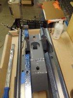
The HS is now 0.0009 inches high and 0.0010" towards the front. This is with the HS bolted down, 1.7" x 11.25" test arbor but still without the bearing caps installed and adjusted or the flat belt installed. Bolting it down did change things a little. So I feel like I am pretty close or at least a huge improvement from where it was. I have struggled a little with the blueing on these parts that can only slide one direction so open for suggestions on improvements to my technique. I have been applying blueing to the bed using a small straight edge, actually a 4" x 1" gauge block. This is something Rese recommended I try.
KIMG1626.jpg
I set the HS in place without the dowel pin and slide it about 3/8 inch in each direction several times. The flat section has streaks of blueing. I thought perhaps dust so cleaned all surfaces and repeated with similar results.
KIMG1622.jpg
Next I did some more work on the lathe bed flat with my 18" angled SE. There seems to be a reasonable number of PPI but the ink on the SE was much more worn at a couple of spots so I worked on those. I can not get any real feel of pivoting due to the size and balance of the SE.
KIMG1625.jpg
I went back to the HS and the marking seems a little better so I am thinking I am on the right track. The streaking is still visible, much more predominate on the flat than the V. So I am guessing this suggests the bed needs more work? Or is this good enough for a bolted connection? Other than refining the amount of blueing used perhaps my next step should be a dry film marking, I have white titanium (red led substitute). Also thinking of trying a 8" precision parallel as a SE.
KIMG1628.jpg


Back
Top