What's new
What's new

Project Schaublin 135

Having followed other forums around the 'Schaublin Slime' issue I wanted to document this part of the process to get to the route of the oil leak issues and the fix too.

Schaublin themselves have obviously during the course of the 135 production and suspect also with other similar models been continuously modifying the set up in terms of oil leak mitigation and one item early on in the dis-assembly process shows this point - spindle oil weep collector.

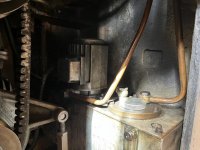
Here is an early example, small capture fixture with copper pipe which empties oil into the gear change housing and subsequently into the return feed to tank reservoir - note no drip tray installed.

0.jpg

My version (late 1970 build) changed design on the capture fixture which also includes a drip tray which extends under the spindle housing, oil expelled into the same change gear location.

IMG_4056.jpg

IMG_4057.jpg

Latest version I have seen pictures of with the same drip tray as the version above.

1.jpg

My machine has the collet changer fitted so have removed the actuator but will show the process to remove the various parts to allow access to the top spindle pulley for access to change the main belt next.
 
Getting it leakfree will be hard IMHO
The beltpulley is caught between 2 labyrint seals which will always leak somewhat
Perhaps limit the flow from the lubepump to those seals somewhat

You do not want a rubber seal there as that generates heat

Peter
 
Peter, I appreciate it might be tough but it should not be impossible, seems somewhat sad that the overall quality of these machines is superb, and over engineered in many areas and yet the design of the pulley wheel is rubbish and not only rubbish but a PITA as when oil leaks is renders the main drive belt useless and out of the two belts this one is the hard one to replace too - overall poor show IMO.

The top spindle area is not an issue as the catch tray and drain work and no oil gets to parts that would suffer as a result so this wont be altered, I may opt to throw out the Schaublin banjo oil feed couplers as I suspect as soon as I remove them to do the work resulting from the oil leak and belt change that they will start to leak too - sods law, so may consider replacing them with some Festo push fit hydraulic fittings and pipe work and remove all the existing copper soldered banjo fittings and all the copper washers that unless they are 99.99% will weep but this will wait until the main pulley system is tackled.

There are a few individuals who are making modifications to convert the pulley assembly into a grease lubricated one and removing the need to feed oil to it at all, I'm watching this to see how easy the work is and what the results are.

I don't plan on replacing the main drive belt after this work for a long time so it will be fixed.
 
GETTING ACCESS TO THE SPINDLE PULLEY FOR BELT CHANGING

The collet closer is straightforward to remove, remover the oiler nipple and gently drift out the pin holding the levered collect mechanism to the mounting ring, once off the ring is removed with three screws set at the back of the plate.

This leaves the mating boss on the end of the spindle shaft, firstly loosen off the Allen bolt on the split collar then on the front of the boss is a wide slot which can be used to insert a length of timber about a foot long into to act as a lever, a sharp tap with a hammer or your hand should see it free off, it is a normal thread so anti-clockwise to remove.

Boss removal technique and removed for inspection and cleaning...

IMG_4058.jpg

IMG_4059.jpg
 
Last edited:
I was told by a 135 user that the two flanges can come off without having to remove the lock ring, the first smaller flag is removed by first undoing the M6 bolts and then inserting M8 bolts into the threaded holes and using them as pullers to left the flange off, it does come away fairly easily this one..

IMG_4064.jpg

Unfortunately the second much larger flange after lifting it out of its location did not want to come fully off, it has a rebated section on the RHS as you look head on which fouled up against the rear of the change wheel enclosure casting, the lock ring just got in the way so had to reseat the larger second flange, something you have to do very carefully as there is a large bearing race which needs to fit inside this flange and its easy to get it locked up (I know!)found the best way was to slowly nip up each bolt a quarter turn in rotation while spinning the spindle to ensure no binding.

So next step is removing the lock ring, two small hex drive bolts pinch the threads to prevent the ring working loose, these are on very tight and would not budge with normal actions so ended up heating them with a fine flame blow torch (my wife's cooking blow torch - perfect for the job) until with care they finally gave in and came out, be careful not to round the hex drive on them as that ring wont come off when they are done up. Once thats done the ring easily spins off with a light tap with a suitable tool on the recesses around the rim, no need for a hook spanner unless you happen to have one the right size that is. It spins off the thread and then again off the thread at the end too to remove, behind it is another machined part which simply slides off past both thread portions revealing the side of the bearing race.

Lock ring off..

IMG_4071.jpg

Now the large flange can be removed, remove the M8 bolts, there are two threaded jacking holes in this flange, one around 11 o/c and one around 5 o/c, the bolts that came out won't be long enough to remove this flange, I ended up using M8x50 which I had in a spares box, wind them in really slowly, half turn each and the flange will come away eventually.

IMG_4067.jpg

Next now the main parts have been removed and the pulley side is visible, it is time to get this off to expose the belt....

IMG_4073.jpg
 
VARIATOR

I am waiting for some 60mm long fully threaded M6 bolts to arrive so I can pull the side cover of the top pulley off so have decided to do some planning and research on how to tackle the Variator oil leaks.

I have cut the main drive belt off as its been soaked in oil for two years and is unlikely to be serviceable, I have a new item ready to go when the work to fix the oil issues are done.

The Variator on the 135's as far as I can understand have gone through several re-designs over the years with naturally the earlier machines having the worst designs - up until early 70's as I understand.

My machine is a late 1970 so has the early version and its challenges are:

1 - The oil feed system is complex and relies on simple seals which fail over time and the resulting oil runs onto the belt effectively rendering it useless.

2 - To access and remove the Variator requires some complex 'surgery' mainly because the shaft that supports the pulleys which make up the Variator is fed in from the back of the yoke/unit and when assembled you cannot simply remove it backwards as the base casting gets in the way. According to a well known German Schaublin repair specialist the reason was that Schaublin did not supply spares for the Variator you just bought a whole new one!

3 - I have been informed that the procedure to remove the Variator is tricky but is as follows:

- Relieve the belt tension as far as possible and remove any belts if damaged or un-useable by cutting off.
- One the back of the threaded screw which is attached to the yoke and is turned by the speedwheel there is a stop clamped to the threaded rod, loosen this and adjust to give max drop of the Variator assembly.
- Remove both oil line feeds from the back of the shaft.
- On the back of the yoke there is an Allen bolt which locks the shaft, this must be loosened so the shaft can be removed

I have been told that if the motor belt is removed and the motor lowered as much as possible, the adjuster can also be removed fully and the motor supported by a jack or similar and moved down this will aid access. The shaft to the Variator 'should' now with some jiggling come backwards out of the yoke and allow the pulleys and assembly to be removed from the machine.

I have yet to try this so will confirm when I have done all the above if indeed the process is successful - fingers crossed.

Newer machines as I believe have a modified castings so the shaft can be removed without any obstruction and even later machines have ball bearings on the shaft so no oil feed and the centre sliding section is just greased - the yoke on the earlier machines sadly (from a man in the know) cannot be machined to accept bearings as the casting does not have sufficient diameter/meat to be machined out and the later machines used a newer casting for the yoke which is not available anymore to buy and when it was it was over £6,000!

Underview of my oily Variator

IMG_4080.jpg

IMG_4081.jpg

Just as a note I am no expert on this topic and have newer owned a Schaublin apart from this one so please if any of the info is wrong or there are bits that could be added to this info post them please as its a huge learning curve for me and I am sure there is lots more to come as I do plan to remove the motor too, it weighs over 100kg but while the Variator is out I want to clean the insides and check the motor over and fix the brake which I understand from a service report done on this machine in 2020 is not working. I'm assuming the brake is attached to the motor as have not even checked?

Once I have the Variator out I will discuss with some colleagues what route to take to fix the oil leaks and post here on the forum.
 

Attachments

  • IMG_4078.jpg
    IMG_4078.jpg
    95.1 KB · Views: 31
45 MINUTES LATER...

Well it's out and yes only 45 minutes which means the instructions are spot on so thank you to Barry for the guidance and for making the work much less of a challenge.

First job was to drop the motor off the adjuster which was achieved by using a piece of wood and taking the weight of the motor by levering it under the front pulley and the base of the lathe cabinet, once the adjuster was removed I lowered it onto some wooden blocks placed under the motor, there is a big hole in the base to allow this to happen.

IMG_4102.jpg

Next removed the stop on the end of the threaded screw on the speed wheel so the yoke could be lowered enough to allow the Variator spindle to be pushed out the back and clear the casting, this was a slightly nervous time as the leadscrew needed to actually go inside the bush casting by about 10mm before there was enough clearance to knock the spindle through. The issue is on the back of the spindle is a large hex section which is drilled for the oil connectors and this needs more space to pass under the casting so I tapped the end of the spindle with a hammer and wooden peg whilst slowly dropping the yoke via the speed wheel until it passed the casting and then you can lift it up a bit as the shaft is smaller in diameter. Not sure what would happen if the threaded rod came out, no doubt there are ball bearings in there and it might be a PITA to redo.

Picture shows the shaft passing under the casting and you can just see the end of the threaded rod in the bushing...

IMG_4105.jpg

The Variator shaft looks like it may have run 'dry' at some point as there is some blue markings on the side of the shaft which matches the pressure points of the pulley loads, I suspect maybe as mentioned earlier in this thread that as oil started to leak the belts started to slip and the user tightened up the belts beyond their safe limit and the forces started to damage the shaft surface and no doubt the brass bearing insert, will check this out as I get further into the strip down.

IMG_4109.jpg

Happy the Variator is out, no clue how to shift the motor at the moment but will remove the oil tank and pump to clean and service this and ponder over how maybe to replace the banjo style fittings with some hydraulic push fit ones to remove the issues with wrongly annealed copper washers (Schaublins own are too hard as I've been reliably informed).

Variator assembly out

IMG_4112.jpg

It would be nice if the shaft could be fed from the front into the yoke but suspect there is not enough room when the yoke rises up into the base unit but might check this for my own sanity as flipping it round should not be a major issue as long as the oil line feeds are able to reach and the bolt to hold the shaft in has a suitable new flat machined on the other end.

The other consideration is now I know where the shaft hits the casting it might be worth investigating removing a semi circle of it to allow the shaft to be removed when its at its lowest point with the stop fitted rather than juggle with it off in future!

Time will tell, now need to get the Variator apart......
 
A LOT LATER......

Sadly the Variator has so far beaten me, I've managed to remove the end threaded collar which in itself was a challenge as it was fitted with a lock adhesive that defied extreme temperature and copious amounts of thumping with a blunt file tip and hammer as I did not have a pin spanner to hand and one of the right diameter (60mm for those interested), anyway it eventually gave up the fight after an hour or so as did the bearing internets and the O ring on the back which I only saw once it came off!

Interestingly this threaded collar is yet another victim of Schaublin modifications, I'm not sure if the collar with 4 external grooves for a 4 pin spanner and no O ring groove is a later or earlier version to mine but yet another example of the changing engineering going on around this 'Achilles heel' of the 135's and others I suspect.

Here is the culprit and the removed and somewhat primitive oil seal, I have sourced a 25x45x10mm Double lip Viton rotary shaft oil seal to replace the ones fitted, I don't believe the ones fitted are still manufactured, Schaublin may carry some stock but I'm not going to use a 50 year old designed oil seal.

IMG_4128.jpg

IMG_4129.jpg

IMG_4133.jpg

The stubborn end of the brass shaft with collar removed, the pulley disc is as I understand a press fit and having spoken to another 135 owner who has just gone through a conversion he said there is a set screw which once loosened allowed his to come off easily, well mine has a hole, challenge is its not threaded and you can see the plain brass shaft at the bottom so either Schaublin have come up with an invisible set screw design or my 'version' was just pushed on with some extreme tonnage and a copious amount of locking agent!!!!

Help please....

Do I head over to a friends workshop and use his 6T hydraulic press plus heat to see if this would budge it or some other method?

If indeed the view is yes would you re-fit the thread collar to use as a base on which to push down or would you machine up a simple adaptor that fits inside the brass shaft and has a lip to push on the rim of the brass shaft?

Either method will require holding the Variator as close to the shaft on the inside of the pulley as I don't want a damaged pulley as that would be expensive I'm guessing - I anticipate this being a PITA too as there is not much room here sadly.

IMG_4130.jpg
 
WEIRD!

Again a design change challenge.....

The gentleman who has recently done his conversion who has been a real help with my endeavours said that his moving centre part of the Variator on his machine is different to mine, my part sits on a what looks like a hardened steel sleeve which slides along the brass shaft, the somewhat concerning thing is this sleeve is just slightly wider that the centre Variator hub and it pops out of each end when you manually move it back and forth, I'm assuming there are O rings inside the main hub assembly but they cannot hold the sleeve in place as well and when the sleeve pops out how is the seal maintained - all a big mystery to me and if anyone has the answers as there are no drawings for this Variator version anywhere then please help me!!

Pictures showing the sleeve right out and the other partially out.

IMG_4131.jpg

IMG_4132.jpg
 
Hi are there any suggestions as to the best route to remove the shaft - will it press out or do I need to consider something else as don't want to damage the brass part as this is an expensive part to replace/make...
 
Well a mate has a 6T hydraulic press as I mentioned in the post earlier but my concern is how to press the brass out without damaging threads and how to hold it as the pulleys make it hard to get any simple support in a press.
 
UPGRADES

While I wait to find a slot to get over to my friend who has the press I've been looking for a few items to test out, new oil seals for the ends of the Variator which seal on the 25mm OD shaft and deal with rotational oil retention and hydraulic compression washers for the banjo oil connectors around the pulley end of the machine.

I'm also considering replacing the main shaft with a new solid 25mm OD shaft and running it in a bearing race at each end of the yoke. I know there is a general feeling the 'meat around the arm ends that carry the current 25mm shaft and are bored to 25mm would not be up to machining out to accept a bearing of say 45-50mm OD which is pretty much the norm OD dimensions for a 25mm ID bore. On this topic I have found a 25x37x7 stainless steel deep groove shielded bearing which might be an option, I'm also considering doubling up these as they are 7mm wide and making them into a twin race 15mm bearing set - still pondering this option.

The second option on the shaft is to machine it down to 20mm OD at each end, I'm thinking that this should still provide the rigidity but allow a smaller bearing choice at the ends, possibly an SKF 20x37x9mm or similar.

Obviously the shaft replacement is a big job but would remove the need for any oil feed to the Variator which was the case with later models which ran bearings on the shaft ends and used a larger casting yoke which sadly is not available but was mega money as a replacement part so probably not a realistic option even if it had been available. Last option and most technical would be to 3D scan the current yoke, re-draw in CAD to add meatier arm ends for the bearings and have the part cmc'd out of solid. I have a friend who can scan and do the CAD work but the machining would be expensive I would imagine and undoubtedly make it unviable financially.

On simpler things have sourced a Viton twin lip oil seal that would work in each end of the current Variator assembly which would hopefully keep oil inside the shaft for a good few years, the seals used on the original are no longer available as I understand so this is something which has to be done anyway.

IMG_4136.jpg

With challenges around the banjo oil pipe connections and weeping and leaks from the copper washers I have bought a few 14mm compression washers for hydraulic hoses and will see how these do when used in place of the copper items, cheap to buy so fingers crossed they deliver an oil tight seal.

IMG_4137.jpg
 
OLD VARIATOR DRAWINGS

In my quest to understand the anatomy of the older oil fed Variator system on the 135 I have scoured this forum and other options with no luck, the later bearing version is available in drawings and most have this but finally I have found a copy of the older oil fed version. I have posted it here for those who need it and hope it helps those like me who are in the process of modifying the current mechanism to make it less prone to leaking......

135-84000v1.jpg
 
SECURING THE BASE

Question for those who have knowledge on this topic, I'm looking at the best way to secure the 135 in its location, I have the Schaublin fine thread screw in adjustable levelling feet collars. The manual shows anchoring bolts into the base (concrete in my case)through these adjustable collars, I appreciate this is one way but could you use feet that have a hard rubber pad on the bottom and use this method which would reduce vibration and not require very accurate anchor fitting or should the lathe be bolted to the ground as per the manual - thoughts?
 
Forgive my ignorance, but does it have three or four supports?

Regardless, I don't see the need to anchor the lathe to the floor. My Monarch 10EE and Colchester Chipmaster are not, and I live in a seismic zone. Any earthquake that would move them significantly or tip them over would be so bad that the lathes would be the very least of my concerns, as in, the whole region would be flattened.

I cowered through the 1989 Loma Prieta earthquake hiding under my desk. SRI, where I worked, had lots of different kinds of lathes and mills, and none tipped as far as I knew.
 
Hi it has 4, one in each corner.

It does seem very 'belt and braces' to actually anchor it to the floor, but I'm wondering if the option to use a slightly pliable foot with a rubber pad is OK or should it just be a solid metal foot so the machine is always level?


Back
Top