Hi, long time lurker here, decided to make an account to say thanks for all the info I've gotten from here and post up the most recent results. I'm a mechanic, welder, machinist, electrician, and have made plenty of animatronics. But machinist wise, I'm still a little green, mostly been a CNC setup/button pusher. This is the first job given to me that was high tolerance, and no print, just make it work again.
So we got an old forming die from one of our customers, and were told to rebuild it.
View attachment 212618

Shop Cat does not look impressed, maybe concerned we won't meet the deadline, or is just unhappy about his picture being taken, I'm not sure.


They supplied the two rings, and top and bottom of the die. Of course they didn't fit, and too much interference to be able to press, so a bit of turning and liquid nitrogen later, and the rings are together.


Next was making the mounting blocks, couldn't weld to the rings since it was hardened 4140. After squaring up the blocks, making the pocket was the next bit of fun. Standard 1" rougher went though like butter, but the 3" long bit did not like that heavy of a cut.


So I backed it off a bit, and got thorugh, then switched to a 4" long ingersoll to remove the last 1/2" and finish the bottom of the pocket. Used a 6" long 2"dia rougher to add a radius to the side, then drilled and counterbored the block. Next was to drill/tap the rings for 3/4-10. So spotface with a 3/4 centercutting endmill, then center drill, drill, and tap. Only exploded one drill bit before I got it right...
View attachment 212615


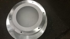
Then on to the bottom die that we resurfaced.
View attachment 212619

View attachment 212617

And finally finished and back together.
View attachment 212616

Shop Cat can now take that smug look off his face, we got it done") Thanks to everyone here for all the info I've absorbed from this site. I still have plenty I can learn, but after finishing this project I've learned a lot and will be more confident taking on more complex projects.
Thanks to everyone here for all the info I've absorbed from this site. I still have plenty I can learn, but after finishing this project I've learned a lot and will be more confident taking on more complex projects.
View attachment 212615View attachment 212616View attachment 212617View attachment 212618View attachment 212619
So we got an old forming die from one of our customers, and were told to rebuild it.
View attachment 212618
Shop Cat does not look impressed, maybe concerned we won't meet the deadline, or is just unhappy about his picture being taken, I'm not sure.
They supplied the two rings, and top and bottom of the die. Of course they didn't fit, and too much interference to be able to press, so a bit of turning and liquid nitrogen later, and the rings are together.
Next was making the mounting blocks, couldn't weld to the rings since it was hardened 4140. After squaring up the blocks, making the pocket was the next bit of fun. Standard 1" rougher went though like butter, but the 3" long bit did not like that heavy of a cut.
So I backed it off a bit, and got thorugh, then switched to a 4" long ingersoll to remove the last 1/2" and finish the bottom of the pocket. Used a 6" long 2"dia rougher to add a radius to the side, then drilled and counterbored the block. Next was to drill/tap the rings for 3/4-10. So spotface with a 3/4 centercutting endmill, then center drill, drill, and tap. Only exploded one drill bit before I got it right...
View attachment 212615
Then on to the bottom die that we resurfaced.
View attachment 212619
View attachment 212617
And finally finished and back together.
View attachment 212616
Shop Cat can now take that smug look off his face, we got it done
Thanks to everyone here for all the info I've absorbed from this site. I still have plenty I can learn, but after finishing this project I've learned a lot and will be more confident taking on more complex projects.View attachment 212615View attachment 212616View attachment 212617View attachment 212618View attachment 212619
Attachments
Last edited:


