What's new
What's new

Rebuilding EXE toolroom surface grinder

cxp073

Plastic
Joined
Jan 27, 2023
Hello

I acquired an old, circa 1959, EXE toolroom surface grinder and am currently in the process of evaluating wear and developing a plan of action to rebuild the machine.

A bit of background. The machine is my first grinder. It was purchased at auction for a nominal sum without being seen. The plan was to expect lots of wear, and rebuild it as a project. I have a novice scraper, having done lathe saddles and the like, but this will be my biggest project.

Full information on the grinder can be found here: http://www.lathes.co.uk/exe-grinder/

When it arrived, it was absolutely filthy. I stripped it down, cleaned everything, and identified that the free screw (z axis) was shot, along with the nut, and the pinion gear for the rack was worn to shreds. Fortunately I was able to source used replacements of much better condition. The motor was originally 410v, so I had this professionally rewound and I had the armature rebalanced. It was reassembled and run using a VFD. The spindle sounds OK, but more on this later.

What I noticed was that the table top, when being fed forward and back (in z axis) showed that the rear of the table was high by .4mm when compared to the front. This was the same across the table. When the table was traversed on the X axis, there was limited variation in the readings. At that point, I thought someone either screwed up grinding the table top, or else the ways were worn (thereby dropping the front, operator side of of the table down). I then slapped the mag chuck on and repeated the rest indicating off the mag chuck, and whilst it needed grinding in, there was nothing near to a .4mm rise from front to the back. Obviously the previous owner solved the 'issue' by grinding the chuck: however this would not work for me as I plan on using the table surface for grinding.

I then took the table off and miked the width of the table at it's four corners. The front of the table was slightly narrower than the rear, but only .1mm so this doesn't account for everything.

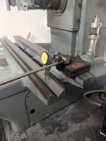
After this, I indicated off the column onto the saddle flat (on the edges, where it is clearly unworn), and traversing the saddle so that I could then indicate off the tops of the (female) vee, again a virgin surface. This showed no deviation in the readings. What this suggests to me is two fold. First, the saddle is relatively square (along it's travel in z direction) to the column. Second, any cause for the slope on the table top would be down to a combination of the table top being slightly thicker at the rear, and that the remainder of the slope must, I THINK, be down to wear in the vee and flat surfaces of the underside of the table and the top side of the saddle. Perhaps the vee at the front is worn much more than the flat at the rear?

I also used a 1-2-3 block on the flat, resting along the edge (a machined 'lip' on the table) so that I could indicate off the vee. Interestingly, this showed that the indicator rise in one direction on one side of the vee, but decrease when indicating off the other side in the opposite direction. I hope that makes sense. I think this suggests that the vee is twisted.

The is the first issue I would like to address by scraping. Getting the saddle top and table scraped in, and hopefully in doing so bringing the top of the table closer to 'level'.

The second issue concerns the spindle. I cannot detect any major axial or radial play when turning the spindle. However, when I really reef on the spindle housing, there is about .04mm of axial play. I believe this actually is caused by poor mating between the spindle housing and the column. It is gibbed. As such, I want to explore the cause of this play further and address that by scraping where necessary.

I am going to post photos shortly, but need to figure out how to reduce their size.

In the meantime, photos can be found here: https://photos.app.goo.gl/JWLEAiX8WFc9pFju6

Any thoughts about what I've posted above, procedure, further checks I can carry out to investigate / be a detective, and then develope a game plan would be much appreciated.

Cheers!
 
Last edited:
Miking the table:
Compress_20230128_094235_5992.jpg
In the following photos you can see the 'virgin' areas on the edge of the saddle guiding flat. I indicated off these, along with the top edges of the guiding vee as seen below. All these readings were equal.
Compress_20230128_094236_6171.jpgCompress_20230128_094236_6343.jpg

Compress_20230128_094236_6508.jpg
In the following photos you can see how I indicated off the sliding vee on the underside of the table. The 123 block is resting on the flat with it's back edge up against a 'lip' on the underside of the table. In the second photo you can see a plus and minus mark on one end of the vee way. This means that when I indicated off that area as described above, and slid the indicator to the opposite end of the vee way, the there was a difference in readings (aprx .06mm if I remember correctly), but in opposite directions for each side of the vee.if you take the first photo as an example, and slid the indicator to the opposite end, the readings would go from '0' to -.06. if you did the exact same operation on the opposite side of the vee, the indicator would go from '0' to +.06. Compress_20230128_094237_7257.jpgCompress_20230128_094237_7424.jpg
I will be taking further photos today so if there is anything in particular you would like to see, please let me know.

My plan of action for scraping the table and saddle top was the scrape the table sliding flat first. I would scrape the virgin areas down first to the lowest level of wear, and use the top edge of the lip, along with the rack mounting surfaces as guides to keep it in line with the original geometry.

I'd then scrape each side of the vee respectively, using the 'lip' on the bottom edges along with a 1-2-3 block to slide along the flat, as I've done above, so as to ensure it is scraped parallel to the table.

Once both sides of the male vee are scraped, I'd then use a precision level to ensure the vee and flat are level with one another.

I'd then move on to the saddle top.

Again, any input on approach or checks I should carry out would be greatly appreciated.
 
Before you start to scrape the table, scrape the top of the table. It is now work hardened and if you don't relieve the hard stiff surface and leave it alone. After you scrape the bottom of the table, fit it to the saddle and then grind the table top the table will bow high in the middle as you will be releasing the built in work hardened stress. I always grind with coolant be it the coolant pump or a spray bottle the table top before I take it apart. Your machine being out so far, just scrape it. You will feel the difference as you scrape. The carbide blade will slide at first and get dull fast. As you get into the softer iron it will grab. :-)
 
You need to make a bolt on lip, a ledge that bolts onto your 1 2 3 block so it follows the same parallel plain. The way it is now you can get a false reading and different readings as it can slide in and out on the flat. File or stone the clearance grove in the table or outside of the table and run the bolt on ledge so your measuring the same places each travel down the table. (Hard to explain by writing) Looking the new pictures of your set up again, I see you have the pins down and the 1 2 3 resting on the ledge, so this will be OK. I helped Keith Rucker make a gage out of 1 2 3 blocks and we bolted them together so no change of error.
 
Be sure to set the table on 3 - Points when making the tests. Even if it is on a flat granite plate, if the table top is twisted it will twist the table bottom and you will get a false reading. Set it on 3 points at 30% from the ends - if you had 3 small rubber pucks or 3 of the same size wood black approx 1 to 2" square. check it both ways and you will see a difference.
 
Richard,

Thank you for your valued thoughts.

Yes, the surface guage has pins as you say and the block is butted up against the lip on the table.

Out of interest, I thought to use the same approach and check the vee on the saddle top. This indicated that the vee is narrower on the right side of the saddle (viewing from operator perspective). I wondered if the sides of the vee would be worn in a similar pattern for the table (each side of the vee being worn more at opposite ends), but it wasn't, it seems.
 

Attachments

  • Compress_20230128_182629_9159.jpg
    Compress_20230128_182629_9159.jpg
    142 KB · Views: 13
  • Compress_20230128_182629_9389.jpg
    Compress_20230128_182629_9389.jpg
    123.8 KB · Views: 13
If the table ways are that worn, the saddle bottom and base are probably worse. That could also be why the reading are so bad on the top of the table. I always say to be a detective and measure everything and don't assume anything. Do you have a camel-back straight edge long enough to scrape the ways? If not, Forum Member Peter and Demon have straight-edges. Plus can scrape if you need any help.
 
I’ll be very interested in following this scrape job.

if the OP is in UK, another straight edge source, in addition to Richard’s suggestions, making new, heat treated (and machined if you want) is Clive Lamb. I think he is Blacksheepcrossmember on Insta.
 
If the table ways are that worn, the saddle bottom and base are probably worse. That could also be why the reading are so bad on the top of the table. I always say to be a detective and measure everything and don't assume anything. Do you have a camel-back straight edge long enough to scrape the ways? If not, Forum Member Peter and Demon have straight-edges. Plus can scrape if you need any help.
I figure they are worn, ideally I'll scrape base, saddle and table - lifting is a problem, so I'm trying tto source an engine crane. Space is limited, so we'll see. I think my neighbours have had enough of me asking for their assistance (I'm sure my surface plate did a back in!).

I thought that the readings taken off the virgin surfaces on the saddle flat, being equal to when the saddle is traversed and indicated off the top edges of the vee, ruled out anything on the underside of the saddle / base as being the culprit for the messed up readings off the table top. Have I overlooked something? If, for example, the double vees on the underside of the saddle / base were worn severely nearest to the operator (essentially tilting the saddle forward and town), then that could account for it - however, if that were the case, I would have expected a similar rise over the virgin surfaces on the flat / vee on the top of the saddle?

I’ll be very interested in following this scrape job.

if the OP is in UK, another straight edge source, in addition to Richard’s suggestions, making new, heat treated (and machined if you want) is Clive Lamb. I think he is Blacksheepcrossmember on Insta.
As it happens, I am waiting on a 30" straight edge from Clive! As soon as I get that, I can get started.

I'm slightly concerned that it may be too wide for the flat on the underside of the table (the mounting surfaces for the rack are higher than the flat, and fairly close to it), but I'll have to wait and see when the straight edge arrives.

If it is too wide, I guess I'll have to scrape the saddle top flat (and vees?) and use that as a template.


I must reinforce - this machine has seen many days of work, but it is just such a great looking thing and with limited space it will, when working properly, be an excellent fit for me. I also see it as a bit of British engineering history, so I'm really hoping I can do it. It'll take time, but it's a challenge.
 
Be sure to check all the ways with the straight-edge even the short surfaces that you will match fit the longer ones too. You have to check to be sure they are not high in the middle. Because if you lay a longer table on the shorter ways that are convex or high in the middle looking like a turned upside down rocking chair bottom and you rub the table back and forth the shorter will blue up all the way along. You can't hinge a V and Flat as they are locked into each other. That's why you need to check all the surfaces hinge with a camel back and if they are high scrape them flat or even a little low in the middle before match fitting the longer to the shorter.
 
I have experienced what Richard is calling a rocking chair. One of the upside-down kind was a big G&L 96" or better (Im not sure if G&L made a bigger sg). It had two big chucks mounted a distance apart and may have ground a production job in its early life traveling too much weight. It would grind fairly flat and then grind the part to go rounded off like an upside-rocking chair. It looked pristine and was bought by a CNC grinder manufacturer. They cut a deal with the seller to have it scraped. Re scraped there is likely not a better machine ever made IMHO+. I have a grinder in my shop now that has a facing-up rocking chair long-way that is the result of too-tight hold-down bolts on its magnetic chuck. I have seen a number of surface grinders like that, belly ways from too tight a chuck, Too tight can actually bend the long table up at the ends. It might grind tenths for some time but is wearing the lower ways thin in the middle.
One hack but Ok/good surface grinder inspection is to set/blue a straight edge on the close side of the ground chuck..often the flatness of the little-used chuck area gives some idea of how flat the grinder might grind... running an indicator off the wheel head on the chuck / and grinding 4 samples about the chuck only tells half the story.
A re-scraped oil way grinder beats almost any grinder one can buy today.
 
Last edited:
I talked to some Mattison scraping techs once and they said they use plastic gage to leave the ways under the electric magnetic chucks I believe they said .002" low when they are done because when the chucks get hot when in use the table grows under them. After years of use the center wears flat and wears the center.

Also I have seen Thompson and G&L grinders left side Vee that is on the back closer to the column and where the git blows that area wear the worse.
 
On a machine that has a close facing of the long table and saddle, or to the base my trick of using a strip of masking tape really works to keep column bouncing grit out of the ways. You smear some light oil on the lower area and then strip 3 layers of masking tape to overlap the opening, then paint the tape and it becomes an invisible and strong barrier. Years down the pike you can remove the tape and find the machine's original paint still intact.

If I designed a grinder I would install a felt wick or a strip of metal to overlap the column side opening. Abrasive Grits flying off the ground part bounce off the column and get into that opening.

...and even trying to be careful, an air hose near a grinder is sure to cause more wear/harm to the machine.
 
It's been a while, but with a very young machinist to train up (i.e. 1 year old), it's slow progress.
I'm running up against 'practicality' issues, mainly lifting related. The table is fine, but the saddle requires lifting equipment or another helper (not a 1 year old!). Unfortunately, I live rural and do not have that to hand. Space is very limited and I do not think I can pull off the space for an engine crane.
Which means, I may have to focus my efforts on the table / top of the saddle.its not ideal, but it is what it is.
I am, however, convinced that the table slope (the fact it is about 20 thou high at the back of table near to column compared to the front of the table, operator side, when indicated off the column traversing the saddle) is a result of wear on the underside of the table and top of the saddle.

Why? Because if I take the table off, and indicate off virgin surfaces of the saddle top (the sides of the flat, and top of the female vees) in the same manner as I indicate off the table (i.e off the column, traversing the saddle front to back), all readings are equal. This suggests, to me, that the saddle is not sloped like the table top is, and that the culprit for the slope must be a combination of wear on the bottom of table (male vee and flat) and saddle top (female vee and flat).

My main goal is to eradicate this slope. I could grind it off, sure, but that's a lot of grinding / removal of metal to rectify wear - a bandaid solution. I'd prefer to rectify the wear as best I can on the ways.

Estimating the wear on the flat, at least the saddle top flat, is easy. I can use a depth mic bridging across the virgin 'sides' of the flat. The vees are less obvious, there is a ridge at the crest of the table vee, but I'm unsure how to utilise this to measure the wear (it is a very thin ridge). In any event, what I *think* I need to do is get the table flat and the table vee parallel to the table top. The flat isn't an issue, but I am stuck on the vee.

In order to eradicate the slope on the table, which obviously would not have been there from manufacture, I think the table flat and saddle flat will need to be heavily scraped, so as to drop the rear of the table top down when it is on the saddle. At least, I think this is the right approach.

In simplistic terms, I would scrape both the table flat and the saddle flat down about 10 though lower than the lowest level of wear (between them my thought is this would drop the rear of the table down by around 20 thou). I would then eliminate the wear ridge on the vee on the underside of the table, and scrape flat (and parallel to reference surface on underside of table). The goal would be to get the vee flat and free of twist whilst minimising stock removal which would have the effect of counteracting my efforts on the flat to drop the rear down. I would make sure the vee is free of twist using a kingway type tool when compared to the flat.

Then I would rough scrape the saddle female vee, and apply the table top as a template. I would then scrape the saddle vee to the table.

Apologies of this is rambling nonsense. Would this be a reasonable approach? Am I completely out to lunch on this one?

As an aside, is it 'normal' for vees to wear much more than corresponding flats? This would reinforce my thoughts..
 
Last edited:


Back
Top