What's new
What's new

Replace or retrofit absolute binary encoder toolchanger?

Garwood

Diamond
Joined
Oct 10, 2009
Location
Oregon
1982 Mori-Seiki MV-45 20 pot toolchanger

It has a Yamatake-Honeywell Binary absolute encoder on the toolchanger magazine that has been giving me fits. The encoder uses a black painted plastic wheel with clear windows to trigger phototransistors. It has a 4" diameter board inside with many resistors, transistors, one small IC and a few capacitors. It has blown a few switching transistors on this board in the 2 years I have owned the machine. Replace bad transistor, good to go for a while.

It has now developed a problem proving very difficult to troubleshoot. When the machine is running for several hours a large current resistor inside the encoder, mounted on the board, gets quite hot, the heat somehow effects the encoder to hold one of the signal transistors on. Right now the transistor for Binary 1 is on so all even number tool pots give an error. The problem floats, so far it has been different Binary values stuck on when it occurs. Once it happens though, the incorrect bit stays the same until the machine cools off and I run it again another day.

At the moment I am running the machine. When the encoder acts up I have the cover off to blast it with shop air, cool it down and it goes back to working fine.

I use a great tech, but he hasn't been able to troubleshoot the problem when it's actually occurred. He's scoped out the encoder, run it on his bench and can't duplicate the problem.

At this point I'm gearing up for a large run of parts. But that said, I don't have the budget to buy this encoder new for $5K or send it off and have it "pro repaired with warranty" for $1500 plus down time.

At this point it seems like my options are-

Mount heat generating power resistor remotely outside encoder housing (temporary stop-gap).

Locate and order replacements for every component on the board and replace everything with modern equivalents.

Get rid of the old encoder entirely and retrofit something modern or go stupid basic and machine a big wheel with microswitches or prox sensors to replace the encoder.

What would you guys do for a retrofit encoder solution? This thing is 24 volt, Binary with parity check and a strobe 0 through 20 in Binary geared 1:1 with the tool magazine.
 
I hope I didn't come off in the above post like I know much of anything about electronics. I'm just trying to stumble through this problem without making anything worse. I can identify most basic components on the board and can use a soldering iron and use ohm and volt functions on a DMM.

So here's a more general troubleshooting question if anyone can offer any advice-

With the enclosure cover removed from the encoder I now have a box fan blowing on the board inside the encoder and the problem has gone away completely. Remove the box fan and the machine errors within a minute with a tool magazine parity alarm.

On a basic component level, what components would be the most likely to change value to point of failure relative to heat?

I was just reading up on testing the photo elements of this board, I don't actually know if they are photo diodes or photo transistors nor how to tell those apart. Thing is, I keep reading that diodes and transistors tend to simply fail. They don't gradually degrade like other things can.

Is this true for the most part about transistors and diodes? If so, would that sort of rule out diodes and transistors from the list of culprits on the board? I can literally put the DMM leads from ground to several points on board traces and components directly connected to the switching transistor that is turning on when it shouldn't be and watch the voltage increase from 2.4 volts (cooled off with air hose) to 2.8 volts where the transistor switches and causes the error. I don't understand the circuit, I can't say what this voltage I'm measuring does or where it's coming from, but there are 7 seperate circuits for the binary encoder and none of the circuits exhibit this symptom. They are either 0 or 24 volts tested at the same places in their circuits.

Most components on the board have been resoldered in the past week with no change to the symptoms. The switching transistors are all new.

Thanks for any advice!
 
Would you be able to post a sketch of one channel with part values of the gizmo? If there's nothing obvious, then there might be a change or two to help. One thing that happened over the eighties is that, for the most part, transistor manufacture became better and more consistant. This could allow changing a few parts values to reduce power consumption.

Actually there are a few things that do degrade - LEDs output power declines with time. After 100,000 hours (about 11 years) the output power can be down a lot. Also, after so many years the plastics used in the optics can haze or at least pick up an oil film. I've found that CD ROM drives after a few years in a shop environment just can't read and a quick cleaning of the lens assembly usually get them going again. Those sensors are less sensitive to films but since they are probably infrared you wouldn't actually see how much they are affected.

Cheers,
 
Garwood, I feel your pain. I work mostly on Moris, and typically older ones. I know EXACTLY what you're fighting, as I've been there, got the dirty T-shirt. Many moons ago, one customer actually spent the bucks to buy a new encoder. I kept the old one and scavenged transistors from it to fix others. Now, we're past that point.

I think this encoder is not binary, but BCD. I've never been able to cross it over to some American equivalent, because it has to match electrically, and it would be reallllly nice for the shaft size to match up. I searched for quite a bit, but after a while, a guy has to go to work and make some money, not sit in front of the disputer all day doing research. Frustrating!

I even considered putting on a common encoder, and adding a cheap PLC to interpret the encoder output, and reconfigure it before sending to the CNC. Considering the price of a new one, that might be extreme, but relatively cheap!

I really wish I had the magic solution. I might someday, but for now, good luck! Let me know when you solve this, so I can do the same thing!
 
Metaltech,

What would make the encoder BCD and not just Binary?

This encoder has five binary channels 1,2,4,8,16 a parity check channel and a "strobe" channel that is on at every pot. It has to output Binary numbers with correct parity and strobe from zero (1111111) through 20 (1001011).

Electrically, the encoder has 9 wires to the Fanuc. +24V supply, GND, strobe, parity, 1,2,4,8 and 16. The 7 channels are just transistors that switch +24V to the Fanuc's input board.

The thing only spins about .5 RPM, doesn't need to be accurate at all (The magazine is hydraulically jambed against a stop pin for pot alignment every time). It seems to me like the only function this encoder has is to give the Fanuc a rough idea where the magazine is at.

I'm giving some serious thought to buying 7 universal prox sensors, mounting them inline and burning out 7 toothed steel discs to replace the optical encoder and all the electronics. I could build this for under $200 and it would always be serviceable.

This Yamatake encoder is actually a piece of artwork in construction, but it's electronics are WAY past their useful life, the paint has begun degrading on the plastic disc (fixed that too), the entire encoder is designed around the optical components that are NOT easily serviceable. Retrofitting modern photo elements would be a big job, the board would need modified, the housing modified, lots of intricate details that have to be right on that are way beyond my experience.

Thoughts on the prox sensor idea? Besides having to cut a hole in the side of the mill's sheetmetal to fit it I don't see a downside.
 
Throughout the day the encoder has gone downhill fast. The box fan stopped preventing the issue.

I was able to slowly blow cold air across the components on the board and watch exactly when the parity error alarm went away. I must have done this 50 times.

I'm now absolutely, positively, no doubt whatsoever, at least 25% sure the problem is a bad resistor.

Spent last 30 minutes, head crammed in 150 degree coolant and chip crusted hole, utilizing several flashlights with different types of light trying to decide whether a band on one of the 31 year old resistors is violet, gray or white.

I think I have it nailed down to gray and the resistor Ohms appear to support this.

Off to Fry's and Radio Shack again!

This could be the miracle component that solves the Yamatake encoder mystery!!!!!

To be continued....
 
New resistor went open within minutes. Suspecting one of the photo receiving elements is crap. The photo elements are beyond my capabilities.

Currently milling new 4" trigger wheel from aluminum and mounting bracket for 7 micro switches.

Plan is to try replacing obsolete encoder with micro switch array eliminating all cantankerous electronics.

I suspect the magazine and toolchanger speed was a lot faster when this mill was new. Over the years and countless repairs things have worn, gotten sloppier, components replaced, misadjusted, etc and the speeds have been slowed way down to keep the toolchanger reliable.

I'm hopeful the microswitches will function fine, but if they do not work reliably I will go to prox sensors or a larger trigger wheel diameter for finer resolution.

As a side, if anyone knows of a mid 80's or older Mori-seiki MV-45, MV55 or MV-65 parts machine rotting away somewhere please drop me a PM if there's a chance I could snag the magazine encoder. The encoder is a minute job to pull off with 4 bolts and 9 wires in the back panel.
 
Have any of you revamped an encoder like this before?

Something I'm curious about is the function of the strobe channel in this encoder. My concern about the micro switches is they will not actuate as precisely as the photo elements did. In the original encoder the strobe on windows are narrower, exactly 1/2 the width of the rest of the channels. My hope is that the control uses the strobe signal as a check so it only registers the rest of the channels when the strobe is on thereby compensating for timing differences when two or more bits change simultaneously.

My fear is when two or more micro switches switch simultaneously the control will register binary numbers that aren't intended as the switch timing isn't perfect.

I'm just curious what measures would be designed into the encoder and the control to filter which signals are correct and which ones are the result of multiple channels switching as close to the same time as mechanically practical. The strobe channel is the only thing I noticed in the encoders design that might be for this purpose.

Thanks for any thoughts.
 
product pictures (929 x 697).jpg

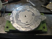
New trigger wheel ready to come off mill. Made it 6" diater instead of 4. Had planned to actuate of the perphery of the wheel, but weighing all the options and what I had on hand to make this work running the switches on the face made the most sense. Made slots .050" deep which seems like too much now that I put a small switch on it. I think .020"-.030" will work better so I will take some material off the face of the wheel.
 
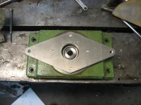
Encoder adapter plate (other side far more elaborate, but didn't want to unbolt for pictures)
product pictures 023 (929 x 697).jpg
Trigger wheel mounted. It's attached to the drive gear with an M10 socket head bolt from the rear.
product pictures 024 (929 x 697).jpg
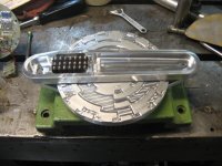
Complete retrofit encoder with microswitches mounted in bridge.
product pictures 025 (929 x 697).jpg

Going to have a beer and dig for some 9 conductor cable.
 
Sorry on the delayed reply. Not enough hours in the day...

BCD would be 1,2,4,8,10,20,40,80. So, lowest 4 bits go 1 though 9, upper 4 bits 10-90. I've got no doc here to look at. I just thought I've seen a chart in the Instruction Manual that showed the codes (as seen on diagnostic page) of each pot position and what the appropriate combination of 0s and 1s would be.

The parts look great. I'm anxious to hear how it works.

Diag parameter 55 shows the control input from the magazine encoder.

The manual has a chart showing the bits for every tool pot number in the tool changer troubleshooting section.

This machine is just binary- 1,2,4,8 and 16. It only makes numbers 1-20 (not zero like a stated above). There can be a tool zero, but not a pot zero.
 
IT WORKS LIKE A CHAMP!!!!!!!!!


Been changing tool after tool in MDI for 10 minutes now without an issue!!!!

I did make one screw up though. I thought the switching transistors in the old encoder switched +24V to signal the input board so I hooked the common lead from the microswitches to +24V (ladder terminal 280). This gave me nothing, the control was seeing pot zero which doesn't exist. I switched the common lead from the microswitches to the ground (Ladder terminal 281) and the SOB works flawlessly. I adjusted the strobe to correspond to the correct pot and we're off to the races!!!!!

After I get some weeks on this thing to make sure everything is A-OK I'm going to make a fully enclosed version of the same thing and have the trigger wheel hard anodized.

Metaltech, feel free to copy this design or let me know if you ever need one and I can whip one up.

The manual I have shows the Binary inputs for the early 80's MV-40, MV-45 and MV-50 so I could likely make the wheels for those as well.

I'm so relieved this worked.
 
Last edited:
To add a little to this for others searching who might have the same problems-

The encoder I replaced is Yamatake Honeywell PT# 7RTA50 20 PB-D5-L2 Made in Tokyo date code 1-82

My biggest concern going to the microswitches was if the control would register minute differences in the switching times of the mechanical switches that had to switch simultaneously to create the next binary number.

The biggest reason I was concerned this would be a problem was because through the last weeks of troubleshooting this thing it was apparent when watching the encoder output on the control screen while rotating the encoder by hand that the control was seeing bits change independent of the strobe bit. After doing the exact same thing with the new microswitch encoder I made I can say the control DOES NOT see individual bits change value independent of the strobe bit. The old encoder was bad, it was simply changing bit values when the strobe bit was on which the encoder should never be able to do.

Basically, the strobe bit is like an "OK Fanuc, it's time to look at the binary number the encoder is outputting". When the strobe is off, the values in the control don't change.

I do not think my fix is superior in any way to the original design, but the original design is obsolete and this appears to work.

This problem caused a lot of lost time both changing tools by hand and editing programs to remove toolchanges. Overall I spent about $500 on professional help troubleshooting the old encoder and the replacement cost zero in parts and took about 3 days to design and machine. All the parts were made on the mill with failed encoder.

If I knew more about PLC's and encoders I think an electronic replacement (as you suggested Metaltech) would be the ideal route to take for long term reliability.
 
This is a fairy tale story about the magician who did not give up and worked hard to make things runing.
Simply fantatstic Garwood. I only can say: HIP HIP HURRAY !!!
And thanks God that we have guys like you here on the FORUM.
 
Credit goes to the experienced guys that share their hard earned knowledge. They make this site great and make stuff like this possible.

When you have old CNC stuff keeping them running is part of your job. I find I have to have the attitude that I will figure out the problem, understand it and fix it. Without determination to keep them alive these old machines would be scrap. With that said, they make beautiful parts when they run and they do run great most of the time. This Mori-Seiki has atleast 110,000 hours of spindle on time on it in it's life. It hasn't had very many repairs considering that and it's still in good shape overall.

The encoder fix has run 9 hours so far.

I did find as the hydraulics came up to temp the magazine started stopping short of the tool called up. I re-centered the new encoder and all is fine now. I didn't have it close enough to center.

The encoder wasn't as sensitive to being perfectly centered before so I believe the new trigger wheel and microswitch arrangement has a bit different dynamic timing than the old setup. When the strobe channel is activated the control drops the stop pin and over-runs the magazine for a preset time to hydraulically jamb the magazine against the stop pin.

When I make another trigger wheel to send out for hard anodize I'm going to narrow up the strobe "bumps" on the trigger wheel to compensate for this.
 
Very well done, Garwood.

As you figured out, this I/O system sees a 1 on a diagnostic when the signal is grounded, rather than having +24 applied to it.

You also figured out that the "on" time of the encoder bits could vary from the switches. In your system, changing the dog width on the wheel would be the way to compensate. A worse way would be to move the switches away from the dog wheel so they travel less, resulting in less "on" time. I'll be interested to see the lifespan of the switches. Prox switches could also be used, but as slow as the dog wheel turns, it might not be an issue.

All in all, a clever bit of inventing. As you say, sometimes you have to go above and beyond to keep an old dog running. Those old Moris aren't fast compared to modern machines, but they're fairly simple designs, with good repairability. Oh, yeah, they're sturdy and rigid as hell.
 
Before I mounted the encoder I assembled it on the bench and put an ohmeter on every switch while rotating the trigger wheel both directions. It wasn't hard to find, but there was a "sweet spot" where all the switches worked well in both directions.

The switches I used are miniature Micro switches with an integral plain follower. If I moved the switches in or out of about a .01" window they would fail to actuate or actually bind up in one direction.

So I absolutely agree that the only way to change the on time is to change the width of a dog.

I would hope the switches will last atleast a few years. I used the switches I did because I have a ton of them. They came in a Vidmar I bought from Tektronix.

Maybe I will make another one with prox switches. Knowing what I know now I think I could come up with a design that would fit in the same space even though the prox switches can't be packaged as tightly.


Back
Top