What's new
What's new

Rewiring from 3 phase 440 to 220 help!

mmarmino

Plastic
Joined
Nov 26, 2014
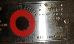
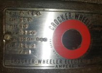
Good afternoon I picked up an old Bradford Lathe. It has a Crocker Wheeler 5hp motor. All the wiring looks pretty good and I am wanting to rewire from 440 to 220 but I do not have a diagram. The wires are clearly marked. White wire to the motor has winding 3/5/9, black has 2/4/8, and red has 1/6/7. I just don't know where to go from here. I will be using a VFD. 20210617_100434.jpg20210617_100456.jpgimage000000(1).jpg
 
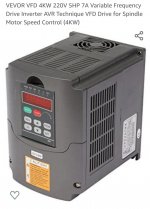
I'm not sure if I have the right VFD because it only says 7A and it appears as though the motor requires 14.2? I get nothing when I press the forward/reverse. But when I force the solenoid up I get a whining sound from the motor. I have reached out to the company but being in China it is probably gonna be a couple days . There area few different settings.However, one review sounded like my application and the person left there settings so I did try those. Anyone else have any experience with this VFD?
 

Attachments

  • 16241319256181350067315717642602.jpg
    16241319256181350067315717642602.jpg
    96.1 KB · Views: 19
  • Screenshot_20210619-154749_Amazon Shopping.jpg
    Screenshot_20210619-154749_Amazon Shopping.jpg
    82.8 KB · Views: 22
Something is wrong in the description of the VFD.

If it is a 4000 watt unit it has to pull more than 7 AMPS at full load. If we multiply 220 volts X 7 amps we get 1540 watts, not 4000 watts. If we divide 4000 watts by 220 volts we get 18 amps.

So:

The 7 amps is a typo and they mean 17 amps?

It's not really a 4KW unit but is 1.5KW?

It's a 440V unit and even then it would still pull 9 maps at full load?

You have the correct unit for the job but you have it programmed wrong?


My lathe is 5HP 220V 3 phase. It pulls 15 amps on start up and 6 amps no load. The VFD is a 10HP unit that will output 32 maps at full load (7KW).
 
Last edited:
From your photos of the nameplate, if you are running it on 220 V then it will draw 14.2 Amps. and that (or higher) is the rating you need on the VFD. The 7 Amp figure refers to using 440 V.

But if it is properly wired for 220 V it should at least start with no load. The fact that you must manually close a solenoid (contactor?) seems to say that it is not wired for 220 V or your VFD is not properly configured. Have you looked for a wiring diagram for the motor?

Larry Dickman refers to a wiring diagram, but does not say where it came from. If it is for a different motor then all bets are off. As far as I know, the various motor manufacturers do not have any standard numbering scheme for the windings. A VOM can be your friend here. It can tell you what is connected to what and what the resistance is for each winding. I would expect any motor like yours would have identical six windings, all of which have the same resistance.


I'm not sure if I have the right VFD because it only says 7A and it appears as though the motor requires 14.2? I get nothing when I press the forward/reverse. But when I force the solenoid up I get a whining sound from the motor. I have reached out to the company but being in China it is probably gonna be a couple days . There area few different settings.However, one review sounded like my application and the person left there settings so I did try those. Anyone else have any experience with this VFD?
 
You need to determine the internal wiring of the motor. Disconnect all the motor leads and check them with an ohm meter per the above diagrams. Note that a delta connected motor will always have 3 sets of leads with 3 wires in each set having continuity. A Y connected motor will have 3 pairs with continuity between the pairs. After you determine that, wire the motor leads to the VFD per the diagram.

If you leave things as in your 1st post, Larry is correct- its a delta connected motor already set up for 220V. I'm probably stating the obvious but nothing new there.
 
Thanks for your input. I will try that first thing in the morning and see what I can find out.
 
You don't want the power from the VFD going through a solenoid, contactor, motor starter or anything else. Run the wires from the VFD straight to the motor. Nothing in between.
 
I did like you said and with my multimeter checked continuity between the 9 wires. With all disconnected I have continuity between ANY of the two I choose. Is this a Y connected motor?

You need to determine the internal wiring of the motor. Disconnect all the motor leads and check them with an ohm meter per the above diagrams. Note that a delta connected motor will always have 3 sets of leads with 3 wires in each set having continuity. A Y connected motor will have 3 pairs with continuity between the pairs. After you determine that, wire the motor leads to the VFD per the diagram.

If you leave things as in your 1st post, Larry is correct- its a delta connected motor already set up for 220V. I'm probably stating the obvious but nothing new there.


Back
Top