What's new
What's new

RSB Camelback

Dsel74

Aluminum
Joined
Feb 23, 2014
Location
Australia
Hi Guys,

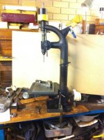
Wondering if you can give me some help with a large bench top camelback. I say large as it is about 40" High, so 30% bigger than a Buke or Junior 10"

IMG_4889.jpgIMG_4890a.jpgIMG_4904.jpgIMG_4908.jpgIMG_4909.jpg

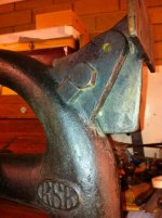
The only real lead I got is an RSB lathe which is believed to have been made in the UK. Been searching the net and can't come up with anything of the same shape let alone another RSB the same.

I want to return it to be flat belt driven.

I think there maybe a thrust bearing missing from the spindle, I have no idea how those locking rings are supposed to be tightened.

It lloks like there is some thing missing from the fixture at the lower back. I guess the lower pulley stack attache here in some way.
 
More photos of my ongoing restoration can be found here.

The Flying XS


I have so many questions and the is so little info I can find. Some photos or adverts for "similar" drills, but they still don't show what is inside!


I'd love to know what mounted at the base? I can only assume it was a bracket for the stepped pulleys.

I deduce there was a two position arm with a locking screw at the elbow with guide pulleys. As the belt turns 90 deg over those guides I am thinking the tangent of the pulley would align with the centre of the drive pulley?? If I figure out the pulleys I can then work out the arc of the arm as it rotates between positions hopefully. Would the guide pulleys have bearings, or just greased up steel on steel? There isn't any bearings any where except for the one (thrust bearing) I believe should have been in the spindle.

How much crowning is required on the pulley and how much wider than the belt would they be?

What size would the second stepped pulley be if the larger was 4½" and how do I calculate the ratio of the pulley at the top to the pulley at the bottom and then to the drive pulley and to the rpm of the motor to get the correct drill speed. That is too much maths for me!

I also would like to know how the remove the chuck from the spindle. My guess is the spindle has a short taper which friction fits into the chuck?


This one might be easier to answer, drill chuck keys do they come in standard sizes?? It is missing on this drill and doesn't match the three keys I have. The chuck is un branded.
 
Hey;

Wish I could help more. I know how frustrating it is to sit out there in the wilderness and cogitate, knowing there must be information... somewhere. I can't say I envy you this task, necessarily, but I sure do pine for a camelback of my own! Here's a wee bit I can impart. Chuck removal. Jacobs knows a bit.

tapered-shank-chuck-removal.jpg


The wedges can be purchased. If there is no shoulder on the arbor, they talk about drilling and pinning the arbor shaft to create a shoulder. Seems extreme, but if the chuck is on a quill it makes more sense. Never done either of those, but I used the third method depicted here. Drill a hole through the end of the chuck inside (if one does not already exist) and drive the arbor out with a rod/drift. That one I know works from experience. I had a bent arbor and replaced it with a new one. Then you can get yourself a nice quality chuck, and if you know the model # you can always look up the correct key.

Although they did seem to take some small amount of time to create a motor bracket with just a little eye-pleasing shape to it, it's a shame when these things get converted to newer technology, and the old bits simply get binned. I can't imagine it will be at all easy to find cone pulleys of the proper style, size, etc. In that light, you might consider making them out of wood. While not exactly correct, it is DOABLE, will get the machine running, and will offer a very nice chance to do something not only creative, but artistic. I can see a very nicely turned and polished set of cones running that old beauty!
 
Thanks Redlineman!

I was pretty sure that is how the chuck would be attached but never removed one before and thought I should ask and not risk damaging it.

I have been going over my options for the pulleys, finding existing ones (unlikely), modifying some steel castors (limited in size & width), making some seems like what I will have to do. I have considered steel, brass, and wooden ones. I may go with wooden ones at least to start with as a prototype, as you know many prototypes end up working so well they never get upgraded.

For the mount bracket I was thinking maybe I could use an old G clamp casting I have that never got past the raw cast stage. I could lay it on its back and run the shaft through where the thread would normally be. Or again it could all be made of wood.

First I need to work out what size they should be and if they need bearings, and what kind roller or bronze.
 
IMG_4961.jpgIMG_4969.jpgIMG_4972.jpgIMG_4973.jpgIMG_4991.jpg

Bit of a clean up, few hours on the pillar. Missing the return spring on the feed handle. And a mock up of pulleys


Back
Top