What's new
What's new

Runn and Start Capacitors for Doerr 5HP 1740 RPM motor... Nidec bought Emerson which had bought Grainger which had bought Doerr everyone says buy new

Pasieka

Plastic
Joined
Jul 22, 2022
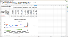
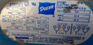
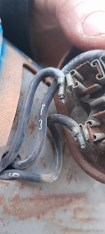
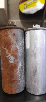
looking for a run capacitor to the 5 HP Doerr motor powering the families air compressor... no-one knows or has documentation as to what is supposed to be... and the cap in it is rusted beyond legibility. compressor is Emglo model Y5B-80V serial 102588029 powered by a Doerr 5HP Motor 5 hp probably made 1988 as that is when the pressure tank was made. the UL and CSA file on it is LR13758 label reads: 5HP 1 Phase 1740 Rpm m184t frame Mtr ref: r75334af881 thinking this is like a model number... 60Hetz, 230 volts, 23.0 amps, SF amps 24.5, SF 1.15 insulation class BR type TX KVA code G and then a final long number in the bottom right that is not labeled is 20(B or 8)046370200 ....it says everything but does not tell me the capacitor sizes. would appreciate a call if someone can educate me on this.. wife is pissed the compressor is still preventing me from finishing cleaning the garage... I am at the point where I want to simply measure current draw and try to dial in a size iteratively. however, I am not sure what my target characteristic setup should be and I am hoping you would advise 773-2258558 is my cell Mark...I used formulas from websites and calculated 98uF if its 84 percent efficient and 91uF if its 78 percent efficient but the efficiency is not specified and I dont know how to extract it from the data available... more importantly another website says a 5hp run cap is never over 40uF so I am begging for help.. will venmo or quickpay BEER MONEY! already replaced bearing and cleaned and painted this compressor up..
snippits from emails I sent to allot of people that may be applicable but basically someone has this motor and if they could remove the cover and tell me what the cap is supposed to be I WOULD LOVE YOU FOR IT
since the efficiency is not specified on the label I am uncomfortable doing the calculation with a 75percent approximation which also gives me an uncomfortable 88.14uF Capacitor and it goes up from there...98.71uF for 84 percent efficiency using this formula....
The single-phase capacitance C(µF) in microfarad is equal to 1000 times the product of power P(W) in watts and efficiency η divided by the product of voltage V(V) in volts square and the frequency F(Hz). The formula for calculating capacitor value is
C(µF) = (P(W) x η x 1000) / (V(V) x V(V) x f)
found on this website calculator:
Single phase Motor Capacitor Calculation calculator | Electrical4u

Maybe this was supposed to be a starting capacitance? but what's in there now is much bigger. This has been occupying my mind for months
and months', searching for a solution...wife is going nuts so i have to finish this compressor off to finish the garage clean up... thinking of trying a 30 uF and then increasing receiving current draw by trial and error on the two legs of the single phase electrical connection and searching for the capacitance value resulting in smallest current but I am just guessing at this point ... what I am thinking is the motor actually spun over in the winter with the blown capacitor so as long as I do not exceed the capacitance I believe I won't damage the motor, I really would appreciate learning a good method of getting to a value as this is not the first time in my life this would have been useful and I'm pretty sure it won't be the last..... I am in a dangerous state, I don't know what I don't know.
 

Attachments

  • cropped.jpg
    cropped.jpg
    776.2 KB · Views: 13
  • 20220315_205724.jpg
    20220315_205724.jpg
    808.4 KB · Views: 16
  • 20220315_155417.jpg
    20220315_155417.jpg
    890.2 KB · Views: 15
  • 20220315_185809.jpg
    20220315_185809.jpg
    815.1 KB · Views: 13
  • 20220315_185815zoomed.jpg
    20220315_185815zoomed.jpg
    537.1 KB · Views: 16
Has the original capacitor top bulged so the contacts inside are open? You can probably get a good idea of the value from the physical size. The efficiency of the motor is not related to the start capacitor value, capacitor is taken out by the centrifugal switch while the motor is running. Almost looks like you have motor run capacitors in the third photo.
 
yes Jim, the run cap in the second picture cannot be measured because the top bulged and severed the internal connections to the terminals. I went and bought a bunch of caps as I had that exact same idea and was going to briefly try each size until one gave me the lowest running current under load.. then I read a bit and found the run cap can advance / increase the voltage on the windings and damage them if it's not exact... so I continued questing for the manufactures specific value... the third photo should have two black cylindrical Bakelite capacitors... those are the start capacitors taken out by the centrifugal switch... this video mistakes T9 for T6 or vice versa but only one exists so it should not be a catastrophic mistake
 
Old bulged compared to new.. in addition to measuring as an open... some photos were to large to upload..
 

Attachments

  • 20220722_124108.jpg
    20220722_124108.jpg
    985.8 KB · Views: 6
yes Jim, the run cap in the second picture cannot be measured because the top bulged and severed the internal connections to the terminals. I went and bought a bunch of caps as I had that exact same idea and was going to briefly try each size until one gave me the lowest running current under load.. then I read a bit and found the run cap can advance / increase the voltage on the windings and damage them if it's not exact... so I continued questing for the manufactures specific value... the third photo should have two black cylindrical Bakelite capacitors... those are the start capacitors taken out by the centrifugal switch... this video mistakes T9 for T6 or vice versa but only one exists so it should not be a catastrophic mistake
The tolerance on the capacitors is probably 20% or so, stop overthinking this.
CarlBoyd
 
The tolerance on the capacitors is probably 20% or so, stop overthinking this.
CarlBoyd
5 percent is current manufacturing tolerance...but multiple reliable sources state winding damage will occur if you are too far from where the RUN cap is supposed to be. this is in series with the run winding and not only regulates current but also timing (phase shift).
 
Show the entire motor - does it have two capacitor housings?

The one you showed (the one that failed) has all the earmarks of a start capacitor. The two black capacitors seem to be run capacitors. Any chance you have them mis-identified?
 
It as two capacitor housings...

T9 connects to the centrifugal switch... one of the terminals of one bakelite cap which is in serries with the other bakelite cap connects to T9 and T3. On the other end....
The other end of the centrifugal goes to the start winding by T7 inside the motor...
The sardine canned ovalcap has T3 and T5 (t5 connected to line voltage in the junction box) to one side and T6 goes to another winding inside the motor... you have me doubting myself at this point.... the two 710- 852 mallory/aerovox bakelite caps in series have a 165 volt rating each... having them in series adds those two breakdown voltages (330 volts).... start caps are usually these larger microFarad components with a range... run caps from my experiences when present with the capacitor start capacitor run motors such as this one...are the lower cap but larger current capable components.... if i oversize the run cap the back emf will destroy the windings by breaking the insulation down with voltage... i believe if i use too small the windings should be safe but i won't have enough torque... so im thinking of measuring current draw and slowley increasing but im just guessing this as an iterative method....
 

Attachments

  • 20220722_161600.jpg
    20220722_161600.jpg
    845.8 KB · Views: 7
Because all bets are off if someone has been in it and maybe installed whatever he had in hopes of fixing his problem. Then you cannot trust anything that you see, unless it is in some way obvious that it is original.....

"Usually", the motor, when under full load, will have the least total motor current when the proper size run capacitor is in place. It is not always convenient to apply a full load condition while you mess around with capacitors............... So it helps a lot if you have some idea what it should have. Then you can at least check that it stays under the FLA shown on the tag.

At some point, unless the motor is the only one you have ever seen like it, is better replaced if it has issues and you have no idea what to connect as far as auxiliary parts (capacitors , etc).

Frankly, unless you KNOW the tank is positively good, i'd consider replacing the whole thing. I won once in that lottery, lost several times. I've had used compressors with perfect factory paint on a replaced Dayton tank pop out a plug of rust and leak down the second time they were pumped up to working pressure. Now I figure any used tank on a compressor is bad.
 
Last edited:
I had a similar problem with a 2000's IR compressor and a 5 HP Emerson motor. The motor kept going into thermal overload and had a high current draw. ESR on the run cap was high and it had leaked electrolyte.The vibration over the years had rubbed off the cap markings. I looked up what the newer 5 HP IR compressors had listed for replacement run caps and bought a total of 5 caps in a series with capacitance from a bit under to a bit over that and tried them all while checking current with the compressor running at the same tank pressure. Used the cap that drew the lowest running current. That was 5 years ago and it has been running just fine.
 
Put a 30 uf in and check the draw you'll probably be done. 30 is very common in 5hp 230v 20ish amp compressor motors replaced lots of em. eKretz do you remember what you ended up with? ALso don't worry about the lowest current just get it to the rated fla.
 
Maybe I missed something, but round plastic capacitors with bleed resistors are start caps. Oval metal caps are run caps and run capacitance is not so fussy that a slight error will kill the windings instantly.

Here's more to read, including this table:
Screenshot 2022-07-23 at 17-32-18 Electric Motor Starting Capacitor Selection - Select an A_C ...png
Any number of suppliers have all the caps - McMaster is a start. Measure 'em up and look in the catalogs for caps in the sizes you have that total the needed capacitance. Move the bleed resistors over, yup, you can solder them to the cap terminals if you do it quickly, otherwise solder them to 1/4" female spade connectors.

Assemble everything, check your wiring, keep your face away from the start caps, power it up. It's only a motor.
 
Put a 30 uf in and check the draw you'll probably be done. 30 is very common in 5hp 230v 20ish amp compressor motors replaced lots of em. eKretz do you remember what you ended up with? ALso don't worry about the lowest current just get it to the rated fla.

No but I can probably take a look and report back. I do remember that in my case, the lowest current drawing cap ended up being pretty close to rated amperage.
 
No but I can probably take a look and report back. I do remember that in my case, the lowest current drawing cap ended up being pretty close to rated amperage.
Make sure you produce a video and put it on U-tube.....:skep:
 
Any insight or feedback would be appreciated... I Thank you guys for participating
What is strange is the total line currents are going down with increased capacitors...
looks like a 30uF gave me maximum RPMs... not seeing anything I'm intelligent enough to identify as significant "AH HA" moment ... maybe you guys see something...
need to remember how to calculate capacitance from current and voltage at run cap and see if that would alight with one of the trials and diverge with others.... there shall be something that excel will surface... or at least that's why I think this experience may be useful for not only this situation...
I cannot believe how NIDEC won't return or answer calls or emails. never buying one of their motors...
I Think my clamp meter was not completely closed for the zero and 10.2 microfarad L Blue current measurements...
I am running with an open tank so barely any load... my logic being the less heat the less likely I will kill the motor conducting the tests
this is a YouTube video of me collecting data for the almost 40 uF test:

Your feedback is appreciated.
THANK YOU!
for some reason I was not notified about the replies to this forum....
 

Attachments

  • 2022-08-03 (1).png
    2022-08-03 (1).png
    139.7 KB · Views: 8
Just checked mine, it's 50μF. Sorry to disappoint you Doug. :D. My compressor's motor is 3450 RPM though, not sure if that makes any difference.

And OP, I were you, I'd be running these tests under load. Short runs for a few minutes at a time won't hurt anything. Get the tank up to 120 psi or so and check your current. Air back down to 120 and check the next. So on and so forth.
 
Last edited:
It's running. Excellent! Now about that compressor that doesn't build pressure....
it will build pressure when I close it up... running these trials without tank being sealed off... did not want too great a load so i have more tolerance before motor is damaged... but cannot run unloaded tests as those would be completely inaccurate... sealed it off after fluid filming the inside and letting it all drip out of the moisture drain... will close and conduct zero to full pressure trials next for 25 , 30 and 35 uF caps... will capture RPM, the three currents and back emf voltage on run cap at 20 PSI increments... hopefully something will become more apparent.. I am going to be looking for that bell curve which was mentioned

Winding Amps x 2,652 ÷ capacitor voltage = microfarads... this is an underload capacitance value from cap voltage and current, but it does not appear to offer any insight as I see nothing trending
 

Attachments

  • 2022-08-04.png
    2022-08-04.png
    154.3 KB · Views: 2


Back
Top