What's new
What's new

Seneca Falls Star Lathe 11”

ejwan

Plastic
Joined
Feb 8, 2022
This is my first post and interested in learning machining.

I am finial getting hands on machining after picking up this Seneca Falls Star Lathe. Been googling the manufacture but not much info for it beside sales catalog vs competitor manufacturers like south bend and etc. it

What I know of the lathe I have is

model: QCE
Advertise as a 11” but has an actual 12” swing
QC GB
Has taper attachment
MT2 tailstock taper
Can’t feel any play in the head stock by hand and the ways looks good to me
Plenty of different style of HSS tooling
The precious owner made a nice motor mount and cover for it attached to the lathe vs hanging it off the wall or table top


Don’t know the year it’s made and will probably never know from the research I found. It does have all the latest and greatest patent so it’s probably in the 1930’s I would say.

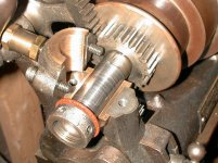
When I loaded it up to the truck the lathe was tilted to load one end at a time on its legs. Some oil spilled out. I started turning and oil every hole I found to try and replace the spilled oil. But the main head stock bearing oil seems odd. Once I added a couple of oil pumps into the hole, using only 10w30 for now, oil found its way out of the headstock squeezing though the bearing towards the chuck. Does that sounds right? I Don’t know where the oil reserves for the head stock is to lube the bearings as it spins to check level. That’s my main concerns now. Didn’t want to fry the lathe already due to oiling.

I would like to post pictures but not sure how this forums handles it

Thanks for any help you can provide

I am also on a quest to find a draw bar and collet set for it and a 4 jaw chuck
 
With the quick change gearbox, it's a later one. I dont think Seneca Falls lathes ever had oil reservoirs for the spindle bearings... just oil cups that flooded the bearings with oil, which then dripped out in a "total loss" style (as you observed).

Sent from my SM-G950U using Tapatalk
 
Oh okay thanks for the clarification Andy. I need to go find the right oil locally to continue chipping. Made 4 taper washer so far.
 
I once owned an older Seneca Falls but sold it to someone else before I finished restoring it to operation.
Maybe you will have already seen the information on Tony's site.
Seneca Falls Lathes and vintage machinery Seneca Falls Manufacturing Co. - Publication Reprints | VintageMachinery.org
I realize they may not answer all your questions .
There are some other threads about Seneca Falls machines on this forum if you try the "Search Forum " feature at the top right of the main page and search for Seneca Falls.
Jim
 
Found a way to put up pictures
30d891d12c567a7cb87ab2adcf49df7f.jpg

Bring her home

a7679055ef3e1e7a29b681b3450d60be.jpg

On the ground

2b2549d1a1f1aa8d152a727d4bd49cea.jpg

View of the gear box

d1b1905daf403b3e63e2fc9c3f4d86ac.jpg

Where oil leaks out off. Pretty fast after filling up the oil reservoir up top with 10w30. It’s the only oil I had at the moment


Sent from my iPhone using Tapatalk
 
I once owned an older Seneca Falls but sold it to someone else before I finished restoring it to operation.
Maybe you will have already seen the information on Tony's site.
Seneca Falls Lathes and vintage machinery Seneca Falls Manufacturing Co. - Publication Reprints | VintageMachinery.org
I realize they may not answer all your questions .
There are some other threads about Seneca Falls machines on this forum if you try the "Search Forum " feature at the top right of the main page and search for Seneca Falls.
Jim

Yea I had a couple of days to research before I could see the lathe. I tried and search as much as I can. After seeing the machine I was surprise it wasn’t sold before I got to it.

I got a steady rest and milling attachment with the lathe also.

The steady rest don’t seem be for this model not sure if anyone can identify the make. Looks to be for a 13” swing lathe. Anyone don’t have a need for a 12” one and want to trade for this one?
5425ccd5e0298d4369c755e0b1a0fb5e.jpg

0a91ed197fbf40cf59333bb2510171c2.jpg


This is the milling attachment but doesn’t look like a Seneca Falls one either. Comparing online looks for like an atlas one. Will need to find a way to mount it eventually.
95d2ebc6f183ed5893749755679929ba.jpg

ef4151a184192fec0c59e778d835def5.jpg


Sent from my iPhone using Tapatalk
 
T could be wrong about this, but I believe the later Seneca Falls lathes used 'ring oiling' on the headstock bearings. The wider bearing caps and shape of them are a clue.

Ring oiled bearings store oil in a reservoir under the bearing called an 'oil cellar'. This is created by designing a 'pocket' in the headstock casting which is located at 6:00 under each spindle bearing. The bearing housings (caps and headstock casting) are made a bit wider then the diameter needed for a plain split bearing. This is to accommodate the oiling ring and allow it to rotate freely on the spindle journal. The bearings themselves are made a bid longer to accommodate a slot for the oiling ring.

Ring oiling works by having a soft metal ring (usually a soft brass alloy) which fits into a slot cut in the top half of the bearing. The inner circumference of this ring contacts the spindle journal at 12:00. The ring is quite a bit larger in diameter than the spindle journal. The lower portion of the ring dips down into the oil cellar.

When the spindle is turning, friction and "viscous drag" cause the ring to rotate (thing of a pinion being turned by a ring gear with internal teeth). As the ring rotates, it passes thru the oil cellar and gets a coat of oil. This is carried up to where the ring contacts the spindle journal. The journal, having a much higher 'surface speed' grabs the oil off the ring. There are likely some oil grooves in the top half of the bearings to allow this oil to be distributed along the bearing and journal.

I suspect the reason the OP is having oil "spilling out" when he moved/tilted the lathe is it came out of the oil cellars.

Ring Oiling, as many of us know from working on older electric motors and other old machinery, usually has the oil cups tapped into the sides of the oil cellars. This is done to maintain oil level approximately tangent to the bottom of the bearing. Given the application in this lathe headstock, Seneca Falls did not put the oil cups off the sides/below bearings on the headstock. Their was method to their madness. Namely, by putting the oil cups at 12:00 on the bearing caps, the designers wanted to insure the bearings were 'pre lubed' before starting the lathe. While I do not have a Seneca Falls manual, it would not surprise me to read something to the effect of:

-This lathe is equipped with ring-oiled spindle bearings.
-Before initial use, fill the oil cups until oil runs out of the bearings to insure oil cellars are filled.
-Before starting the lathe for use each day, fill the oil cups. Some oil may run out of the bearings, particularly when the lathe is started.

My guess is that Seneca Falls designed a simple 'recirculating' feature in the headstock bearings. The bearing caps and headstock casting are a bit longer than each bearing. An internal groove is machined in the caps and headstock casting at the end of each bearing. There may be a drilled hole that comes off these grooves at 6:00 and angles down into the oil cellars. As the spindle rotates, oil tends to form not only a 'wedge shaped film' between the spindle journal and the bearing, but the oil also takes something of a helical path along the journal. This helical path takes the oil to the ends of the journal/bearing, and it is slung off into the internal groove in the bearing cap/headstock. The drilled hole then allows the oil to return to the oil cellar.

I do not see any means of telling if the oil cellars are full, so am guessing that Seneca Falls followed the "K.I.S.S." rule of engineering (Keep it simple, stupid). Again, method to their madness. Telling lathe operators to oil the headstock bearings before each use insured not only prelubrication of the journals (which would not otherwise get oil until the lathe started turning), but insured the oil cellars were kept topped up.

I also would not be surprised if Seneca Falls had given instructions for the maintenance of the lathe including something to the effect of:
"Once each year, disassemble the headstock spindle bearings and clean out the oil cellars using kerosene"

The almost inevitable final question asked by owners of old plain bearing lathes like this one is: "What kind of oil should I use in the headstock and other bearings ?"
My answer is: Use an ISO 46 oil, and this can easily be obtained by buying a jug of "Tractor Hydraulic Oil" in ISO 46 weight. Tractor Hydraulic Oil is what I've run in my own old machine tools for many years. Tractor hydraulic oil is, aside from being ISO 46 (about 20 weight) or ISO 68 (about 30 weight), known as a "DTE" oil. DTE = "Dynamo, turbine, engine", an oil classification predating the automobile. DTE oils are mineral oils, and tractor hydraulic oil will contain only an anti-foaming and corrosion inhibiting additives. ISO 46 is a straight-weight oil, no additives which would hurt 'yellow metal' parts, and is pretty much what would have been used way back when.
 
I’m pretty sure Joe M is correct about the headstock bearings. I have a 10” Seneca Falls lathe. The headstock oilers look just like your photo and my lathe definitely has ring oilers just as Joe described.

Dave
 
T could be wrong about this, but I believe the later Seneca Falls lathes used 'ring oiling' on the headstock bearings. The wider bearing caps and shape of them are a clue.

Ring oiled bearings store oil in a reservoir under the bearing called an 'oil cellar'. This is created by designing a 'pocket' in the headstock casting which is located at 6:00 under each spindle bearing. The bearing housings (caps and headstock casting) are made a bit wider then the diameter needed for a plain split bearing. This is to accommodate the oiling ring and allow it to rotate freely on the spindle journal. The bearings themselves are made a bid longer to accommodate a slot for the oiling ring.

Ring oiling works by having a soft metal ring (usually a soft brass alloy) which fits into a slot cut in the top half of the bearing. The inner circumference of this ring contacts the spindle journal at 12:00. The ring is quite a bit larger in diameter than the spindle journal. The lower portion of the ring dips down into the oil cellar.

When the spindle is turning, friction and "viscous drag" cause the ring to rotate (thing of a pinion being turned by a ring gear with internal teeth). As the ring rotates, it passes thru the oil cellar and gets a coat of oil. This is carried up to where the ring contacts the spindle journal. The journal, having a much higher 'surface speed' grabs the oil off the ring. There are likely some oil grooves in the top half of the bearings to allow this oil to be distributed along the bearing and journal.

I suspect the reason the OP is having oil "spilling out" when he moved/tilted the lathe is it came out of the oil cellars.

Ring Oiling, as many of us know from working on older electric motors and other old machinery, usually has the oil cups tapped into the sides of the oil cellars. This is done to maintain oil level approximately tangent to the bottom of the bearing. Given the application in this lathe headstock, Seneca Falls did not put the oil cups off the sides/below bearings on the headstock. Their was method to their madness. Namely, by putting the oil cups at 12:00 on the bearing caps, the designers wanted to insure the bearings were 'pre lubed' before starting the lathe. While I do not have a Seneca Falls manual, it would not surprise me to read something to the effect of:

-This lathe is equipped with ring-oiled spindle bearings.
-Before initial use, fill the oil cups until oil runs out of the bearings to insure oil cellars are filled.
-Before starting the lathe for use each day, fill the oil cups. Some oil may run out of the bearings, particularly when the lathe is started.

My guess is that Seneca Falls designed a simple 'recirculating' feature in the headstock bearings. The bearing caps and headstock casting are a bit longer than each bearing. An internal groove is machined in the caps and headstock casting at the end of each bearing. There may be a drilled hole that comes off these grooves at 6:00 and angles down into the oil cellars. As the spindle rotates, oil tends to form not only a 'wedge shaped film' between the spindle journal and the bearing, but the oil also takes something of a helical path along the journal. This helical path takes the oil to the ends of the journal/bearing, and it is slung off into the internal groove in the bearing cap/headstock. The drilled hole then allows the oil to return to the oil cellar.

I do not see any means of telling if the oil cellars are full, so am guessing that Seneca Falls followed the "K.I.S.S." rule of engineering (Keep it simple, stupid). Again, method to their madness. Telling lathe operators to oil the headstock bearings before each use insured not only prelubrication of the journals (which would not otherwise get oil until the lathe started turning), but insured the oil cellars were kept topped up.

I also would not be surprised if Seneca Falls had given instructions for the maintenance of the lathe including something to the effect of:
"Once each year, disassemble the headstock spindle bearings and clean out the oil cellars using kerosene"

The almost inevitable final question asked by owners of old plain bearing lathes like this one is: "What kind of oil should I use in the headstock and other bearings ?"
My answer is: Use an ISO 46 oil, and this can easily be obtained by buying a jug of "Tractor Hydraulic Oil" in ISO 46 weight. Tractor Hydraulic Oil is what I've run in my own old machine tools for many years. Tractor hydraulic oil is, aside from being ISO 46 (about 20 weight) or ISO 68 (about 30 weight), known as a "DTE" oil. DTE = "Dynamo, turbine, engine", an oil classification predating the automobile. DTE oils are mineral oils, and tractor hydraulic oil will contain only an anti-foaming and corrosion inhibiting additives. ISO 46 is a straight-weight oil, no additives which would hurt 'yellow metal' parts, and is pretty much what would have been used way back when.

Thanks for the detail explanation! I hope the reservoir is full. Do you think this is the drain or full level for the oil? If it’s the full screw is there a way to flush out the oil?


35d610f010059d0f7b054f0020e64477.jpg
 

Attachments

  • IMG_4343.jpg
    IMG_4343.jpg
    1.9 KB · Views: 12
Last edited:
Don’t know why I am unable to upload pictures like I did early. I’ll try and attach a better picture when I can

I’m pretty sure Joe M is correct about the headstock bearings. I have a 10” Seneca Falls lathe. The headstock oilers look just like your photo and my lathe definitely has ring oilers just as Joe described.

Dave

Thanks for confirming. It is a better oiling system vs me trying to figure out if it’s dry in a middle of chipping to add oil


Sent from my iPhone using Tapatalk
 
That steady rest looks like it’s for a Monarch 10EE.

Thank you for identifying the steady rest. It would help in my swap with another owner easier.

Not sure how the previous owner ended up with the different brands in tooling. The machine looks to be very low use and I am surprise more of the original tooling from Seneca disappear over the years before I bought it.


Sent from my iPhone using Tapatalk
 
I bought some tractor hydraulic oil iso 46 per Joe Michaels recommendation should be arriving today.

Ended up turning 6” along an aluminum rod to check for straightness. I got about .002-.003 taper from end to end. Not bad for not having to rebuild the old girl.

3c1a07a110859101bab77fd13543b2de.jpg


But since I am new. When applying the live center how much pressure should be exerted on the work piece? I did notice that when I did apply some decent pressure the headstock shifted away a bit. I need to setup a dial indicator to see how much the shift is. What is the acceptable tolerance for the thrust washer for a machine like this?


Sent from my iPhone using Tapatalk
 
Ejwan:

I am glad to read/see you getting into using your Seneca Falls Lathe. Seneca Falls built their last lathes of the type such as you have in 1948.

In answer to your questions about force on the live center & spindle thrust bearing adjustment, I will try to give you some answers.

How tight to make the tailstock when running a live center on a smaller lathe is (at least in my opinion), a matter of experience and feel. On long/small diameter work, too much force from the live center can cause the work to buckle or bow. On softer materials, too much force on the live center combined with the side-load force from the cutting of the work can also deform the center hole.

My own method on smaller lathes/lighter work, is to tighten the tailstock until I cannot turn the live center with my fingers or hands, then give the tailstock handwheel maybe another 1/8 of a turn.

Bear in mind that as you turn work in the lathe, it develops heat. This heat will cause the work to expand lengthwise, putting more force into the live center as well as into the chuck or whatever other means at the headstock you are using to support/hold/drive the work. As the length of job increases, the growth due to expansion also increases. Chances are the live center bearings are more than adequate to take this force. Where things start to go askew is with the work itself. If the work expands and is restrained against 'growth' from that heat/expansion, the result on longer/thinner work is a buckling or bow in the work. When you let the work cool and back off the tailstock/live center, you may find some deviation from the diameter you started with at the tailstock end vs. diameter at midpoint of the job. It's a good idea to be aware of how much heat is building up in a job in the lathe which is supported on the tailstock center. If you are taking heavy roughing cuts and seeing the cutting oil and chips smoking (I kind of doubt that you will take a heavy enough cut to get the chips turning blue), back off the tailstock center and then run it back in so it is snug, checking that you cannot rotate it with your fingers. This relieves the force developed from the expansion of the work during the time you are turning it in your lathe.

Seneca Falls, on the really old lathes, used a simple thrust adjustment. The most usual direction of thrust from turning and threading operations pushes the spindle towards your left as you face the lathe. There is a collar machined onto the spindle, and this collar bears against the front spindle bearing to take that thrust load. No adjustment needed. To take the thrust load in the opposite direction (towards the tailstock) and to keep the spindle from walking or moving axially in the headstock bearings, Seneca Falls used a pair of adjusting nuts and thrust collar/thrust washer on the small/left end of the spindle. I base this on a 10" Seneca Falls lathe, built about 1903, which we had years ago. Seneca Falls, or some machinist who used that lathe along the way, had made a thrust washer out of 'reinforced phenolic' (aka "Micarta" or "Bakelite"). I suspect this was not original to the lathe, as reinforced phenolic material had not come into use at the time the lathe was built. Most likely, the thrust washer was made of a hard grade of bronze. If your lathe has a thrust washer, there should be:

-adjusting nuts on the small end of the spindle (these may have slots for a hooked spanner wrench)
-hardened & ground steel thrust washer
-bronze thrust washer
-hardened & ground steel thrust washer which runs against the outer end of the left-end headstock spindle bearing

Method of adjusting:
-loosen both adjusting nuts (the outer of the two is used to lock in the adjustment on the inner nut)
=tighten the nut closest the headstock until you cannot turn the headstock spindle by means of your hands on the headstock cone pulley. Do not get crazy and tighten this nut hard. Just enough to bind the spindle and take out the end play.
-Back the nut off in very small increments until you can turn the spindle with your hands and not binding is felt.
-Lock in this adjustment by tightening the outer nut while holding the inner nut with a hooked spanner (a hooked spanner is kind of like a curved claw with a bend end that engages the slots in the circumference of the adjusting nuts). It is important to hold back on the inner nut, as tightening the outer nut to lock the adjustment can 'take the inner nut along for the ride' if you did not hold back on it.
-If you are curious as to end play, you can set the end play using a feeler gauge between the thrust washer and the headstock spindle bearing's end face. I'd use a 0.002" feeler gauge, and make sure you can get it removed with only a light drag felt on the feeler gauge. Same as adjusting valve lash on older motorcycle engines or other engines. Snug up the adjusting nut until you can just pull the feeler gauge out and work it back in between the thrust washer and end of the headstock bearing.
-If you are equipped, you can do this same thing using a dial indicator, but you will need to force the spindle in one direction to take out the end play, then back against the indicator to measure the end play.
-If the Seneca Falls lathe has a ball type thrust bearing (you will know this when you look at the thrust bearing), tighten until you take out the play, then back off slightly until a light drag is felt, but you can still turn the spindle by hand. Lock in the adjustment as above.

I'd say about 0.002"-0.004" of end play is plenty for a lathe like an old Seneca Falls. Again, this is based on the idea that most of the thrust force in lathe work is going to be directed towards the headstock, not away from it (towards the tailstock).
 
It might be worth taking a look under the spindle bearing caps on your lathe to see what's really there. It also looks like there may be shim between the lower and uppers on those bearings. Often in older lathes the 'fit' of the spindle bearings was adjustable by tightening or loosening the screws holding them down. My older 9" seneca falls lathe has simple bronze bearings, it had no shim under the caps and the spindle could be locked completely solid by tightening the screws on the caps. I put shim in there to set the clearance.

The oilers were very simple, just copper tubes that protruded above the top cap by a bit. I replaced them with home-made wick oilers.

The left hand bearing on that lathe, open for inspection:

(also, the fiber thrust bearing that Joe discussed is visible. It bears directly on the bronze spindle bearing side, to prevent right-ward motion of the spindle. This lathe has a loose ball thrust bearing to prevent leftward movement)
 

Attachments

  • SF_gear05.jpg
    SF_gear05.jpg
    96.7 KB · Views: 41
Joe and Jim I will certainly give the thrust clearance an inspection soon. I read up on inspecting the bearing clearance is commonly done by spindle head rotation drag feel and using a dial indicator to pry up and down on the head stock with a bar. But I rebuild 3 car engines before and have bore gauge with 10 thousand accuracy. Would they be useful for this scenario? I do realize the brass would be a negative to being scratched easily.

I’m very appreciative on the answers I got thus far! I was worried about buying this machine vs a more common one with plenty of info to rebuilt from others online that already exist. I would be scratching my head on how to approach a deeper inspection of the machine. I am truly grateful for all the help and hope one day I can pass it on to another member/person seeking help.

Looks like I made it out okay with the purchase. I don’t think I stated how much I got it for. I got it for $400 and paid another $55 for the live center since it was missing.

As long as this machine is able to help me learn threading inside and outside and make round tools I am all in.


Sent from my iPhone using Tapatalk
 
Pulling headstock up/down and checking with indicator should get you going. There are enough variables to worry about without having the headstock moving! If you don't have a lot of lathe experience look into how to grind HSS tools. A lot of my early troubles were due to not fully understanding what face on the tool is really doing the cutting and in what direction is that force being applied. This video helped me understand what was going on. https://youtu.be/__A2xtLF0AU
 
A bore gauge is not needed to check/adjust the headstock spindle bearing clearance. I've written the procedure for checking/adjusting the clearance in the type spindle bearings your Seneca Falls lathe has, posting it a few times over on this 'board. The method of using a dial indicator mounted so its contact tip touches the spindle at 12:00, as close to, and on the 'outboard side' of each bearing is what is used to check clearance. Slacken the drive belt, put the quadrant gear selector (the knob that lets you choose which way the lead screw will be turning) in the neutral position, and back off on the thrust adjusting nuts when doing this test.

For a lathe the size of yours, a hardwood hammer handle will work fine. Stick it into the spindle bore and push down HARD. This squeezes any oil out of the bearing. Zero the indicator and pull up on the hardwood handle with about 75 lbs of force (not critical, just don't get wild and act like King Kong). Read the indicator while pulling up and holding the hammer handle. That is your bearing clearance. It is adjusted with shims at the split joint of the bearing.

As I suspect, your lathe may well have ring oiled bearings, so you have to be careful in disassembling and reassembling the bearings to set the clearance.Shims have to be cut and positioned to allow the oiling ring to rotate freely on the spindle journal, and the ring must be located in its slot in the upper bearing half when you go back together.

Before taking anything apart on the headstock, and before you snug up the thrust adjustment, check bearing clearances. I'd say if the front (chuck end) of the spindle has not more than 0.0015" (0.002" at the absolute most) for clearance, your lathe will be OK. The rear bearing, being smaller, will have 0.0015" maximum clearance, with a little under 0.0015" (about 0.0007-0.001") being what I'd look for.

Your lathe is one of the later Seneca Falls lathes. You got a bargain, given its condition and what came with it. I see the micrometer carriage stop, amongst other things. South Bend Lathe's timeless classic "How to Run a Lathe", while written around South Bend Lathes, gives spot-on information for what a light duty lathe of the design of yours, as well as the grinding of tool bits for machining the work. Mr. Pete has a good youtube series on basic machine shop work, and includes how to grind tool bits, and uses a wooden mock-up of an enlarged tool bit to teach with. Ultimately, as you grind tools, you will learn what works and produces a good surface finish on the work. Use your God-given gifts of the senses and your mind, as this, like anything else in life, is best learned by our own doing. It's like learning to ride a bicycle or much else. Teaching, even youtubes on a subject, can only take a person so far. HSS toolbit blanks are cheap enough, and you grind a toolbit blank at each end, so you get 'two fer one'. The proof of how well you ground a tool is in the surface finish and the chips. Clean, well formed chips rather than jagged chips, and a good surface finish and a lack of 'chatter' (vibration and audible screaming from the lathe tool/work) are what tell the tale. We all start somewhere and we all must never stop learning.
 
Joe, you gave much good advise. I would only add that when grinding tool bits they need to be stoned after. L look through a 10 X loupe will show the benefit of stoning with a fine stone to get rid of the grinding marks.


Back
Top