What's new
What's new

Single point threading NPT on a CNC

lucifex

Plastic
Joined
Apr 30, 2023
So whenever i get to make a part with an npt thread on or in it me and my coworker have always struggled. We have some working programs for the cnc lathe with offset notes and whatnot.
We have the gauges for the internal and external threads we need to make. But instead of struggling everytime another npt nightmare arrives i want to figure out where im messing up. Because it cant be that hard right?

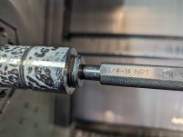
So tomorrow i need to make a 3/4 inch internal npt thread in a part.
I plan on doing it this way.
From kennametal there is a thread calculator where i will pick 3/4npt and it will spit out the major and minor diameters at both ends of the thread
To make internal threads i have to make a bore up to the minor diameter.
I will start off with an 20mm(0.7874 inch) insert drill and profile the bore.
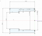
My bore will start at the minor large diameter(23.665 mm/0.9316 inch) and taper down to the minor small diameter(22.799 mm/0.8975 inch) over a length of 13.861mm/0.5457 inch with a few mm of straight bore to give my threading tool a litle room to taper out and give me a straight surface to measure the bore.

N1T101(ROUGH)
G0G40X19.Y0.G96S80M3
G0Z2.M8
G71U1.R0.2
G71P300Q400U-0.2W0.02F0.22
N300G0G41X25.
G1Z0.
G1X23.665
G1X22.799Z-13.861
G1Z-18.861
N400G1X19.
G0G40Z50.
G0G53X-50Y0.Z-350.M1

N2T202(FINISH)
G0G40X19.Y0.G96S120M3
G0Z2.M8
G70P300Q400F0.12
G0G40Z50.
G0G53X-50Y0.Z-350.M1

Profile in inch mode
N300G0G41X0.9842
G1Z0.
G1X0.9316
G1X0.8975Z-0.5457
G1Z-0.7425
N400G1X0.7480

After that i will draw up the thread with a 5mm(0.1968inch) lead in and a 2mm(0.0787inch) lead out to calculate my start and end point.
I start with the major large diameter(26.510mm/1.0437 inch) and the major small diameter(25.644mm/1.0096Inch) the length and extend that line in the z positive for 5mm(0.1968inch) to synchronize the spindle and in the z negative direction by 2mm(0.0787inch) to make sure my toolpath is long enough.
We always use a two line g76 when threading so the will look something like this

N3T303(NPT 14X60 )
G0G40X19.Y0.G97S800M3
G0Z5.M8
G76 P020060 Q60 R30
G76 Z-15.861 X25.52 R-0.62 F1.814
G0G40Z50.
G0G53X-50Y0.Z-350.M1

converted to inches

g0z0.1968
G76 P020060 Q60 R30
G76 Z-0.6244 X1.0047 R-0.0244 F0.0714


Last time i did it like this i had to adjust the bore dimension and the thread up in x by about 0.8-1mm to get it to gauge right so obviously i am doing something wrong.
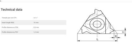
I did figure out i didnt account for the tip of the threading insert
so i offset the threading path by 1.2mm(0.0472inch) that helped a litle but i still had to offset quite a bit.

Can anyone of you help me figure out what im doing wrong because im feeling pretty stupid by now.

Thank you
 

Attachments

  • 3-4npt.png
    3-4npt.png
    70.8 KB · Views: 26
  • 3-4npt bore.png
    3-4npt bore.png
    76.4 KB · Views: 27
  • NPT G76.png
    NPT G76.png
    80.2 KB · Views: 19
  • insert.png
    insert.png
    83.8 KB · Views: 17
  • NPT G76 inch.png
    NPT G76 inch.png
    66.8 KB · Views: 21
  • 3-4npt bore inch.png
    3-4npt bore inch.png
    73.2 KB · Views: 16
Last edited:
The first time I did it, I too had to adjust my X offset a bit. Once you get the proper fit, use your X offset to change your X in the program to reflect it. You're using the Metric mode to cut an Imperial thread, so I assume you have converted everything correctly. I'm not Metric fluent, so I won't attempt to visualize your tool path. Also, why do you have a Y in the program?
 
I'm using a y axis lathe so i'm just making sure its on center, Mostly im used to offsetting my threading tool about 0.15mm(0.0059inch) to get them to gauge nicely on straight threads. 5 times that ammount (about 1/32 inch) seems like im doing something wrong. The imperial/ metric thing also kinda messes me up because im not imperial fluent and most of the machining internet seems imperial focussed. I will add the imperial numbers in my post
 
If your tool is defined by the tip, you want your g76 path to be based on the 26.51 dimension (or it's offset). Otherwise you aren't cutting anything.
 
If your tool is defined by the tip, you want your g76 path to be based on the 26.51 dimension (or it's offset). Otherwise you aren't cutting anything.
That may have been what i changed last time i did 1/2 npt. i will have to check in the morning.
 
N3T303(NPT 14X60 )
G0G40X19.Y0.G97S800M3
G0Z5.M8
G76 P020060 Q60 R30
G76 Z-15.861 X25.52 R-0.62 F1.814
G0G40Z50.
G0G53X-50Y0.Z-350.M1

Your taper is close, but not correct. The overall length from your start point in Z to the finish point is 20.861, therefore, the taper amount as a radial value is 20.861 x 0.0625 / 2 = 0.652.

Also, the X value in the G76 Cycle for an internal taper thread should be the Major Diameter at the small end of the Internal Taper and therefore, the R value in the second G76 Cycle will be R+0.652

Regards,

Bill
 
I'm at the machine right now. I turned my profile and when threading the tool scratches the surface on the first or second pass. However the tip broke off before it could finish the cycle. Do I have too oversize the bore above the minor diameter?


PXL_20230501_102705296.MP~2.jpgPXL_20230501_102715764.MP~2.jpg
 
Typically when I am single pointing threads I will typically take more than one pass, especially something as big as a 3/4npt.

I'm sure there are a lot of people here who laugh heartily at the idea of 3/4npt being a big thread, but the most common sizes we cut or tap are in the #0-#4 range.
 
What kind of holder and insert ? Tip breaking off is usually too brittle an insert or too crappy a holder, not the program.
I am using an 11IR.14.NPT CCN20 insert from CERATIZIT. In a generic holder for this type of insert its a 16mm/~5/8 bar with minimal projection.

When I intentionally overcut the bore to about halfway between the major and minor diameter my gauge went in to the right depth, although the thread now had big flats on it. This tells me my threading path is right, and my bore is off. The threading insert takes a beating when it has to cut this much material at the crests.
Is there any reference material specific for the tapered bore size and depth?


Typically when I am single pointing threads I will typically take more than one pass, especially something as big as a 3/4npt.

I'm sure there are a lot of people here who laugh heartily at the idea of 3/4npt being a big thread, but the most common sizes we cut or tap are in the #0-#4 range.
The g76 cycle is specifically for threading the Q value determines the cut depth. My cut depth is probably way too low if anything. 3/4 is about the average size we do when single point threading just not tapered.


On the backside of this part is also 3/4 npt external this time, when i look in that kennametal calculator and apply the same logic the thread gauges fine first try. Is that just dumb luck?

Thanks for all your inputs by the way :)
 

Attachments

  • Sub-spindle external profile.jpg
    Sub-spindle external profile.jpg
    3.2 MB · Views: 14
  • 3-4 external.jpg
    3-4 external.jpg
    5.2 MB · Views: 13
  • 3-4 external gauge.jpg
    3-4 external gauge.jpg
    4.8 MB · Views: 7
  • Bore Gauge.jpg
    Bore Gauge.jpg
    5.8 MB · Views: 11
  • Oversized bore.jpg
    Oversized bore.jpg
    4 MB · Views: 15
  • Threading insert.jpg
    Threading insert.jpg
    6.8 MB · Views: 24
  • Threading Bar.jpg
    Threading Bar.jpg
    4.7 MB · Views: 21
  • Sub-spindle external thread.jpg
    Sub-spindle external thread.jpg
    4 MB · Views: 17
The g76 cycle is specifically for threading the Q value determines the cut depth. My cut depth is probably way too low if anything. 3/4 is about the average size we do when single point threading just not tapered.


On the backside of this part is also 3/4 npt external this time, when i look in that kennametal calculator and apply the same logic the thread gauges fine first try. Is that just dumb luck?
And do you have problems when cutting an Internal, Parallel Thread? There should be no difference just because one is tapered. Yes, 0.05mm is a very small first pass DOC. To result in a somewhat efficient threading operation using the G76 cycle, typically the first pass DOC is as much as the Threading Insert and the Workpiece Setup can consistently tolerate. The algorithm used to calculate each successive DOC, measured from major diameter of an External Thread and the minor diameter of an Internal Thread, is as follows:
DOC = SQR(N) x Q
Where:
N = The Nth Threading Passs (1,2,3 etc)
Q = The First Threading Pass DOC

When applying the above calculation, the resulting DOC is used until the difference between the Current DOC and the proceeding DOC becomes less than the value specified by the "Q" address in the first G76 Block.

As the "Q" values in both G76 Blocks are the same, all Threading Pass DOC will be the same.

For a G76 Threading Cycle, what does the Kennametal calculator do for you? Most of these calculators spew out long hand, threading pass by threading pass data.

Regards,

Bill
 
Last edited:
I am using an 11IR.14.NPT CCN20 insert from CERATIZIT. In a generic holder for this type of insert its a 16mm/~5/8 bar with minimal projection.

Are you threading on the way out? Sorry I didn't go through the code, but that insert looks like crap. The wear is showing on the back side and the edge is all rounded over and the nose is chunked off and it just looks bad as bad can be. Maybe CarbideDinosaur will head this way and take a look but ... it looks like you are only cutting on one flank and if there's any tilt to the insert it's the wrong flank, looks short and sturdy enough but the wear pattern, ugh ?

Besides the program, that insert appearance would make me sad.
 
And do you have problems when cutting an Internal, Parallel Thread? There should be no difference just because one is tapered. Yes, 0.05mm is a very small first pass DOC. To result in a somewhat efficient threading operation using the G76 cycle, typically the first pass DOC is as much as the Threading Insert and the Workpiece Setup can consistently tolerate. The algorithm used to calculate each successive DOC, measured from major diameter of an External Thread and the minor diameter of an Internal Thread, is as follows:
DOC = SQR(N) x Q
Where:
N = The Nth Threading Passs (1,2,3 etc)
Q = The First Threading Pass DOC

When applying the above calculation, the resulting DOC is used until the difference between the Current DOC and the proceeding DOC becomes less than the value specified by the "Q" address in the first G76 Block.

As the "Q" values in both G76 Blocks are the same, all Threading Pass DOC will be the same.

For a G76 Threading Cycle, what does the Kennametal calculator do for you? Most of these calculators spew out long hand, threading pass by threading pass data.

Regards,

Bill
When cutting straight threads I metric or imperial I don't have a problem. I think that's because I only have the diameter to worry about and not the z depth. On a typical thread I would start with a bigger q value but as you can see the insert doesn't like whatever I'm doing.
 
When cutting straight threads I metric or imperial I don't have a problem. I think that's because I only have the diameter to worry about and not the z depth. On a typical thread I would start with a bigger q value but as you can see the insert doesn't like whatever I'm doing.

Can you try this with real threading code instead of those stupid cycles ? At least you can see what's going on when you do it that way. And you can make it do what you want, and watch each pass to see where you are going wrong.

I hate those dumb arfing cycles on a lathe, can you tell ? :D

I'm still ??? about why the insert is showing wear on the wrong flank ? And normally these days, after being lectured by the tool guy, I go straight in rather than doing the one-flank angle-in 29* kind of thing. You might have to try both ways here tho to see which works better. I wonder if that threading bar has any tilt at all, it looks a little off-brand ? I am a big fan of the laydown sandvik fullforms but still any kind of tool should at least work, even if the results are not the best possible.
 
Last edited:
Can you try this with real threading code instead of those stupid cycles ? At least you can see what's going on when you do it that way. And you can make it do what you want, and watch each pass to see where you are going wrong.

I hate those dumb arfing cycles on a lathe, can you tell ? :D

I'm still ??? about why the insert is showing wear on the wrong flank ? And normally these days, after being lectured by the tool guy, I go straight in rather than doing the one-flank angle-in 29* kind of thing. You might have to try both ways here tho to see which works better. I wonder if that threading bar has any tilt at all, it looks a little off-brand ? I am a big fan of the laydown sandvik fullforms but still any kind of tool should at least work, even if the results are not the best possible.

I've switched the bar out to another brand, both have an angle to the insert seat. Also changed the cycle to straight infeed didn't help much. Best result is changin the doc to 15 . And letting it take like 50 passes
That gave me multiple parts on the insert

I had to oversize the hole from my calculations so I think that's my problem. 316L also isn't the nicest material to figure this stuff out, but this batch cuts quite nice.
 
Can someone give me the info for 25e external taper thread fitting. The big and small diameter, angle and the pitch? I’m doing single thread milling on master cam.


Back
Top