What's new
What's new

Spindle gear for Stark #4 Lathe

IMG_20210708_164304~2.jpg

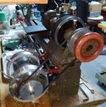
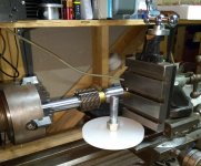
Making up a belt pulley for the variable speed DC motor. The thought is to pivot the motor from the back 3/4" rail and use gravity for tension. If the motor is free to be positioned along the rail, it may be possible to use all 3 of the spindle pulleys along w/ the variable speed of the motor.

I am going to experiment and try making a 1 1/2" wide Velcro belt to go with it
 
IMG_20210714_200609~2.jpg

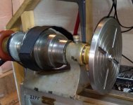
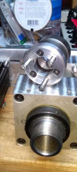
Looks like the only way to get 4S collets is to make them ! This plug will be used to mount a faceplate. It works fine in the headstock, but the thread is actually too long.
 
IMG_20210715_201519~2.jpg

The faceplate is a new old stock Craftsman rescued from EBay. The collet was made from a 1 1/2" stainless shaft cutoff from a ballscrew.

IMG_20210715_201550~2.jpg

The Velcro "belt" is waiting for the motor mounts.

Did some facing tonight with the stepper drive. 5 thou stainless cuts. The stepper likes slower speed as the current is still set to minimum. The motor should take the full current available w/ the SX6 drive. We'll see.
 
Last edited:
you might be fine with your motor and using gravity to tension the belt, but I found that I had to positively tension my DC motor > countershaft belt or I'd get motor bounce. The motor pulley would ride up the belt a little bit and then drop back repeatedly, which introduced a fair amount of vibration. my motor was mounted on a pivoting plate, so I simply added a bolt to the bench so that flipping the countershaft lever raised the motor against the bolt.

Be a bit tricky to do if you want to slide the motor along a rail to get all three spindle speeds, but not impossible. I had a similar set up to switch between 2 different pulleys on the motor, so used 2 bolts, one for each end of the motor plate. Ended up never using the larger motor pulley though, lathe ran plenty fast enough.
 
I think you are right. I was trying to lay out parts and think what the constraints were.

IMG_20210716_180213~2.jpg

Sliding might work, but I would have to have 3 individual belts. That's not a problem, but I will still have to figure a positive tension.
 
I wouldn't take that as gospel, it's a function of motor weight and (I think) pulley size, so you may well be fine.

Cool looking motor set up! I'm guessing it's going to be direct drive, going by the pictures? Ie. no countershaft? If so, one way to tension the same belt on the 3 different spindle pulley ratios would be an over center tensioning lever (like on a South Bend) with 3 different mounting points on the ring that holds the motor. They'd need to be different lengths, to account for the sliding, and not interfere with each other, but that's one way. Another would be to pull the motor down, but that would require something behind the lathe which might be awkward to use.
 
I'm guessing it's going to be direct drive, going by the pictures? Ie. no countershaft? If so, one way to tension the same belt on the 3 different spindle pulley ratios would be an over center tensioning lever (like on a South Bend) with 3 different mounting points on the ring that holds the motor.

I like that idea, the over center tensioning lever ! If I use 3 belts I might get away w/ a single lever with a compession spring in the rod. (?)
 
how would you keep the 2 untensioned belts from interfering with each other and the tensioned belt? No need for a spring on the tensioning lever, but you'll need either a left/ right threaded bolt for adjusting tension or have some means of allowing the threaded rod to rotate at one end and screw in/ out at the other end.

I did the 2nd option for mine, as I didn't have thread cutting capability at the time (and it was easier)
IMG_0215.jpg
 
Update:

Been using the "temporary" stepping motor to clean up the face plate. The slots has been cleaned up by boring to 3/8" so that the cheap 8mm t-bolts can be used, the surface has been faced and a removable center installed. I found that the ordinary Parker SX drives (cheap on EBay) can still do following like the expensive F models. The ratio can be set for any TPI.
On this setup I get vibration unless the spindle is turned very slowly due to the offset mount and rubber belt drive. It would probably work for milling threads if the encoder was turning with the x-axis handle. In Continuous Mode it does make a nice variable speed drive, although it should be geared down to increase the torque. At least now I should be able to turn the spindle gear !

The Rivett adapter shoe was too wide for the Stark bed. I've super-glued in a pair of brass shims to stiffen that up.

I haven't made another collet stub yet. The first one was great except for the single point threading. I have a 1"-20tpi die on order now.

The DC motor mounts are looking so much like a steady rest that it may all become one project.

IMG_20210724_192619~2.jpg

Organization for domestic harmony....
 
IMG_20210725_115223~2.jpgIMG_20210725_115454~2.jpg

The idea of an electronic "thread chaser" w/o modifying the Stark has me thinking. I've modified a grinder mount to fit on the tool holder. If I clamp an encoder onto the X-axis compound feed screw the SX6 will let me control the spindle at any ratio (ie. TPI) desired. This is backward from the usual setup and you still have to feed the compound by hand. Still the ability to mill any thread on the Stark might be worth it.
 
Current Misadventure: Time to bore out the 50-tooth spindle gear.
The 4-jaw chuck refused to mount on either Stark. It must have been fitted to some other 1 3/4 - 10 spindle ? The thread on the backing plate measured slightly off center, just undersize and w/ a slight taper. Picked up the thread after centering and kept taking a bit off (and remounting etc)at a time and trying it on the #183 Stark until it fit. Now I'll take it home and try it on #2295. If it fits, I should be able to center and bore the gear.

Fits perfectly now !
 
Last edited:
IMG_20210728_195050~2.jpg

Ok, but now I have to find some 1/8" key stock !

(This Stark cuts so smooth I couldn't believe it. Almost don't miss power feed, as this was faster, I think, on something like boring a gear.)
 
While scaling up the gear train drawing from the Levin lathe threading option, I noticed that the 50P gears would scale to 22P for the Stark #4. This may (?) be why they were in this lot of Stark parts.
 
Countershaft option. I was fortunate to get the matching three step flat belt countershaft pulley with my #4 Stark. I used a countershaft motor mount from a 9” South Bend lathe. The set up works well with a 1/2hp three phase motor and VFD.

I fixed a 40 tooth 16DP gear (had a set from something) to the end of the spindle with the intent of rigging a threading attachment of some kind. I haven’t built said attachment yet so I will be following this thread closely. I do use the gear and gear tooth sensor to feed a spindle tachometer so it’s not completely decorative.

Hope this helps.

Ben
 
When the motor mounts are finished I will have the choice of the DC or stepper motor w/o interfering w/ the gear train. I like the Levin setup w/ a flex rod (or maybe cable) drive to the x-axis. The old Stark compound from #183 has threads that can be accessed w/o modification. The Rivett compound thread would need to be modified.

The gear set that I have only has primes to "7". The gears are: 100,90,80,75,70,60,50(4),45(2),40(2),35,30,25 in 22DP. I should probably be looking for a 127 in 22DP, but I need to learn about the metric thread sequence.

I am going to scale up that Levin setup by 2.25X and try some layouts on paper. img34.jpg

Do you have a serial # for your Stark ? (I haven't figured out how to date them yet.)
 
IMG_20210801_142131~2.jpgIMG_20210801_143716~2.jpg

Here is the gravity mount w/ 2 different belt lengths. It will need shaft collars to keep the axial position.

Finally got around to measure the pitch angle of the 22DP gears, 14.5 degrees.
 
Last edited:
Update: Replaced the squeaky stepper w/ the one I thought was burned out.

Managed to lose 2 of the 22DP gears, the 90 and a 50, so a bit of change of direction.

Found a 22DP hob on EBay (OUCH!) and revived a project to make a step spindle from a short piston cylinder. The adapter from a cast iron fitting mates to the Stark collet chuck.

IMG_20210805_182952~2.jpgIMG_20210805_183007~2[16457].jpgIMG_20210805_183732~2.jpg

We'll see if the Stark can cut gears. Need to make up some arbors next. It will be a challenge to get the geometry set up right for the helical hob.

I think to try putting the hob on the main (x) lathe axis and the indexed disk (gear to be) on y. Possibly the compound could set the helix offset angle ? Need to work this out w/ what parts I can find around.
 
Last edited:
IMG_20210807_131031~2.jpg

Tapping 3/4-32 w/ 3-in-1 as fluid

IMG_20210807_132608~2.jpg

Apparently successful, this will become the 3/4" mandrel nut. Probably finer than needed but it's what is available. I'm trying to see if this setup can also be used as a series chaser to single point cut the threads on the mandrel.
 
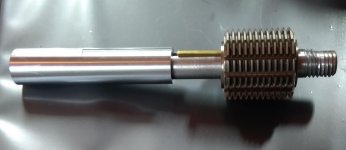
First try at hob arbor...

IMG_20210809_174542~2.jpgIMG_20210809_174419~2.jpg

Hardest part was the key slot..added a flat for the 4-jaw chuck to index. The screwed up thread on the right is from the broken shaft that supplied the material.
Still have to thread and mate up the nut.
Looking at GB185602896A.pdf, the 1856 British patent N2896, by Christian Schicle.
Hab Patent.jpg

So far.....

IMG_20210810_161653~2.jpg

The center from the bent end is still a problem.
 
Last edited:


Back
Top