What's new
What's new

Spindle gear for Stark #4 Lathe

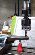
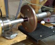
The gear blank holder (shown w/ gear) as carved from pneumatic cylinder piston shown above.

IMG_20210815_072455~2.jpg

Reusing scrap parts can save a lot of time (esp. on a WW lathe) and often means better material.

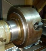
The 4-jaw chuck needs a new backplate, the imbalance that it causes is a pain to work around. There may be a way to center it for now until the Stark can cut threads.
 
A quick Trim-N-Shim of out of round on the backplate reduced it's OD by .022" and shimmed with .010" material greatly reduced the chuck offset.

IMG_20210817_080829~2.jpg
 
The support arms keyed and fitted to the milling attachment.

IMG_20210817_163917~2.jpg

Need to fit the gear blank shaft next. (the disk is just for illustration)
 
Last edited:
Update: slow going...

IMG_20210821_104929~2.jpg

Bored the arms for bronze bushings. This went well using the original shafted piece to line up the holes in the drill press.

IMG_20210821_080508~2.jpg

The shaft itself has been a problem. The extension threaded on the end still has a wobble. This will have to be redone.

The lathe now has good centers. A MT2 live center has been shimmed w/ .020" stock and now fits.

IMG_20210821_132917~2.jpg

The assembly is probably usable as is, but not really smooth enough.

IMG_20210707_213016~2.jpg

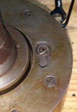
Finally found out (by disassembling) that the slot on the back of the chuck was to change between simultaneous and independent jaw action !
 
Inside the 4S collet-mounted chuck...

IMG_20210904_110711~2.jpg
IMG_20210904_103940.jpg
IMG_20210904_103950-a.jpg

There is a ring shaped cam that rides on the back of the ring gear to engage or disengage the the chuck jaws. The cam is accessed through the slot on the back face of the chuck. There probably was a threaded pin and a thumb nut there originally. I have not found a picture of that.
 
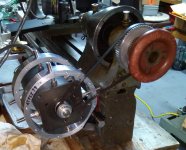
The setup w/ a 70 tooth gear for lineup.

IMG_20210905_160003~2.jpg

It looks like the 66 tooth gear may be the minimum tooth count for this configuration as it stands. It should be able to get to 127. Replacing the compound w/ a direct mount is one possibility for smaller gears, inverting the setup may be another.
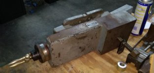
 
The setup w/ a 70 tooth gear for lineup.

View attachment 328413

It looks like the 66 tooth gear may be the minimum tooth count for this configuration as it stands. It should be able to get to 127. Replacing the compound w/ a direct mount is one possibility for smaller gears, inverting the setup may be another.

Edit: Either the cross-slide will have to be used to set the hob angle or the cross-slide will have to be mounted along the bed rather than perpendicular to it, as the compound cannot be be brought into close enough alignment to the cross-slide due to the interference of the dials. Fortunately, both of those arrangements are possible on the Stark.
 
4S collet plug number 2 also made from a cutoff piece of stainless ball screw.

Before...
IMG_20210901_134538~2.jpg

After...
IMG_20210906_122442~2.jpg

The thread came out much better this time, but the newly acquired die would not start on this material w/o cutting a rough thread. Burred like crazy. The die was more like a self-correcting thread gauge. Only carbide wanted to cut this stuff, light cuts.

I'm looking for suggestions on what to make that would be a useful accessory and be characteristic of the Stark lathe.
 
Setting the hob angle of 1 degree, 28 minutes.

IMG_20210913_102543~2.jpg

A 1/16 pin is superglued to the Rivett alignment block to gauge the angle from the block corner using the trig tables.

Mandrel to mount series of gear blanks and trim the diameters.

IMG_20210913_152659~2.jpg
 
Last edited:
Progress on the gear cutting is very slow. Still need to find a good stepper for the secondary axis.

The gravity mount and the spindle stepper drive has been working very well. The same mount should be fine for the DC motor in the future.

IMG_20210920_164121~2.jpg

Slowly building up a 4S collet collection.

IMG_20210920_170232~2.jpg

Edit: just found more steppers...hope springs eternal !
 
The new stepper seems to have enough torque to do the job, enough to make the timing belt slip.

IMG_20210927_100252~2.jpg

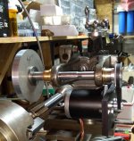
To counter that, another new extension for the mandrel has been made on the Stark, this time much more carefully as the compound is very touchy.

IMG_20210927_100121~2.jpg

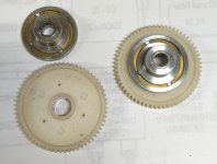
The drive for the mandrel is being switched from the timing belt to gear drive. Plastic gears from a pair of junkbox clutches are to be bolted solid.

IMG_20210927_100408~2.jpg

These plastic gears drove steel gears, so if the plastic doesn't work out the mount would have to be rearranged so that the steel gears would fit.
 
Last edited:
With a fair bit of frustration finding time to work on it, and a small rush job which needed the Stark, it looks like the gear drive is the best so far. No tension between the shafts to account for.

IMG_20211008_175447~2.jpg

This is probably not the final pair of gears (or belts) but it seems to work well enough to allow trying out different schemes to synchronize the shafts.
 
The cobbled up drive system for the 2 steppers.

IMG_20211012_090732~2.jpg

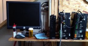
Monitor, cheapest PC I could find, now running XP w/ free software from Parker, ( XWare )and 2 surplus SX drives. This is what was available for a temporary fix. It will be an involved calculation with all of the belt and gear ratios being used at the moment.
 
Last edited:
A very pleasant surprise !

The clocks in the SX drives are so good that all one has to do is set the speeds of the 2 steppers independently and they stay in synchrony. No programming, just calculate the ratio for the gear setup, plug in the speeds and go.

This has only been tested w/o load at this point, so its time to set up and try cutting a gear.
 
First gear test in Nylon (?). 54 teeth, a little deep (~ .100"), fed at .025" per turn.

IMG_20211017_160718~2.jpg

The angle needs to be tweeked. I need to find a better way to set it.

IMG_20211017_160945~2.jpg

Fuzz has to be removed on the back side.

IMG_20211017_160827~2.jpg

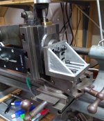
Changed the mount to use the Stark compound. Very old but in better shape than the Rivett.

IMG_20211017_150011~2.jpg

Went back to a belt drive to gain some finer motion from the 200 step servo.

IMG_20211017_145349~2.jpg

The main drive has a 20 to 62 reduction. This test was at 60 RPM. The secondary has a belt reduction of 3 times, so the secondary runs at 60/54 RPM.
 
Ran a couple more tests in plastic, but decided to improve the rigidity somewhat by reversing the hob mandrel and setting the slides for maximum overlap. This meant reducing the travel to 2 inches, but that's just a bit more than enough. The next attempt will be with aluminum.

IMG_20211026_203119~2.jpgIMG_20211026_203236~2.jpg

Forgot to mention, the homemade angle gauge for the compound is absolutely essential to an easy setup !

Edit: Setup still needs to be made more rigid for Al 0.005" depth of cut. Trying to reduce the effective lever arm.
 
Last edited:
Well, aluminum didn't go all that well

IMG_20211107_073957~2.jpg

The compound does not have enough friction to resist the torque when trying to cut metal. No problem with power. Waiting for some phenolic before trying again. Giving some thought to improving or making a better mount for hobbing. I'll probably have to find or make a dedicated cross slide that can be locked to the bed.

Back to cutting tapers with more success this time. The method used was to hog down to about 15 thou above final dimension, then blue and fit each pass against the socket, tapping the compound to correct the angle on each pass. Finally, stone the taper to get rid of the turning marks or at least minimize them. The result locks easily into both the headstock drive plate and the tailstock ram (on this lathe). Not a ground finish, but the performance is much better than hoped.

IMG_20211102_113000~2.jpg
IMG_20211106_112040~2.jpg
IMG_20211107_073613~2.jpg
 
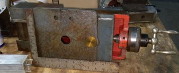
So far, this is the only slide I've been able to scratch up. No idea what it came off of, but it's way more than beefy enough. Probably have to remove a considerable amount of metal to make any kind of reasonable fit.

IMG_20211124_101649_2.jpg
IMG_20211124_101551_2.jpg


Back
Top