What's new
What's new

Static balancing rig

ARB

Titanium
Joined
Dec 7, 2002
Location
Granville,NY,USA
So if you fellas wanted to make a static balancing rig for balancing a lathe chuck. What would you use for bearings?

I am thinking about making a low friction stub spindle (A2-6) that i can mount a CNC lathe chuck onto and and try to get a better balance on one of my cast turning jobs. I have thought about dropping the belts off the spindle to see if that would be free enough to half assed balance the assembly.

How free is a lathe spindle without the belts? (Non Gearbox)

100_3340.jpg


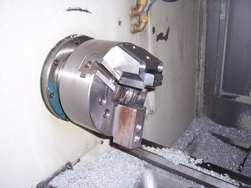
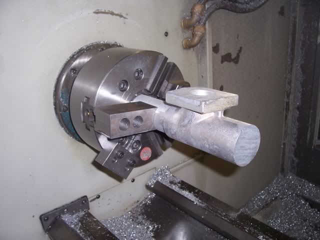
This contraption holds a casting that is not balanced and I would like to be able to turn it more than 1200 RPM without it shaking like a wet dog.


Any Ideas?
 
I don't have any ideas for the balancing ring, but have you thought about modeling the whole thing in Solidworks? That will give you the CG so you can play with weight and locations until your balance looks pretty good.
 
What about making a spindle to your nose specs, fitting chuck etc and adding weight to the other end then balancing on a grinding wheel knife edge type set up?......... can't get much less friction that that;)
 
Joe's modeling suggestion could be a big time saver as compared to any other approach that involves making stuff. From the picture, it looks like the part itself is cast aluminum and not too large in diameter. For a first go at it, I'd model just the jaws and "attach" them to a round disc to get the collective CG location, since imbalance is so heavily dependent on the distance of the mass from center of rotation. Looks like it'd be easy to model them. Of course if you've already got a model of the casting itself then it'd be easy enough to merge it into the rest of the solid, but getting the CG of the jaws themselves back to the Z centerline oughta help a lot.
 
The more I think about it the better Solidworks sounds. I already have the fixed jaw modeled and the part is rough modeled. I would just have to clean it up a little.

The part is basically a pipe with a big flange hanging off the side of it making into a T shape. Between that and the fixed jaw she likes to shake a little.

It sure works slick though.
 
A very nice effort in making a two jaw chuck from a three jaw.

Can you fatten up the moving jaw? Probably doesn't apply to your setup.. *sigh

Regards,

Stan-
 
Thanks,


Part of the problem is the flange hanging off the part is off to one side of the jaws further complicating things.:rolleyes5:

Fattening up the moving jaw certainly would help. And I will probably find I need to add some weight there.

I think I will figure out the balance without the part then compare it to the balance point with the part.
 
NIce job on the 2 jaw! I like the Solidworks idea best, but if you want to go quick and dirty, it looks like you are light on the moveable jaw side- you could probably trial and error an improvement by adding weights to the chuck mounting bolts on both sides of the moveable jaw and adjust weights as required. I think I would keep weight off the jaw itself as the less weight on the jaw the better for clamping force.
Dan
 
You need 2 lobe shaped rings that will clamp to the chuck OD. You start with the lobes 180° apart, approximately 90° to the imbalance. You start moving them in equal amounts toward the light side and ramp up the spindle and check, rinse and repeat until you get it balanced.
 
Here it is with the part.
100_4792.jpg

You need 2 lobe shaped rings that will clamp to the chuck OD. You start with the lobes 180° apart, approximately 90° to the imbalance. You start moving them in equal amounts toward the light side and ramp up the spindle and check, rinse and repeat until you get it balanced.


About how lobie?:)

Any chance of a pic?

Sounds like a good idea.
 
Here it is with the part.

About how lobie?:)

Any chance of a pic?

Sounds like a good idea.

The lobes need to weigh more than the offset in your part. It really does not matter how much over, but don't get excessive. The _important thing_ is that they each weigh the _same_. The closer you get to the offset mass of your part with your balance ring weight, the farther from the 90° position they will be when the assembly is balanced with a part in place. We've been doing this for decades for offset features.
If the rings weigh the same, at 180° apart, they are balanced, so there is no effect. Only when you start moving them off the 180° set-up does it have an effect. This is why you need 2, side by side.

See attached thumb for a visual representation. One hint: Engrave degree markers from the ID outward 1/4" or so long, around the hole.

It _does_ take patience to set up correctly as it's trial and error, but if you do it systematically, it doesn't take very long to do. Once you get it balanced, scribe the chuck and weight rings, so you can put them back if you change the machine over.
 

Attachments

  • weight lobe.jpg
    weight lobe.jpg
    15.8 KB · Views: 390
Here it is with the part.
100_4792.jpg

Wow, how would you determine where the heavy point is to start with, other than in a solid modeler? The fixed jaw is at one angle, the feature is at another, and they are of different weights and lateral locations.


ARB - what prevents you from holding that in a 3 jaw - is there a hidden feature?
 
ARB - what prevents you from holding that in a 3 jaw - is there a hidden feature?
There is a sanded parting line that causes headaches when using a 3 jaw.
We started running them that way and it was problematic. Then I went to a manual 2 jaw chuck to prove the concept. It worked great but running a chuck wrench got old. Plus I was swapping chucks all the time.

This works perfect for this part. I would just like to run it a little quicker with less shake.


The lobes need to weigh more than the offset in your part. It really does not matter how much over, but don't get excessive. The _important thing_ is that they each weigh the _same_. The closer you get to the offset mass of your part with your balance ring weight, the farther from the 90° position they will be when the assembly is balanced with a part in place. We've been doing this for decades for offset features.
If the rings weigh the same, at 180° apart, they are balanced, so there is no effect. Only when you start moving them off the 180° set-up does it have an effect. This is why you need 2, side by side.

See attached thumb for a visual representation. One hint: Engrave degree markers from the ID outward 1/4" or so long, around the hole.

It _does_ take patience to set up correctly as it's trial and error, but if you do it systematically, it doesn't take very long to do. Once you get it balanced, scribe the chuck and weight rings, so you can put them back if you change the machine over.
Thanks a bunch Tony!:cheers:

I will be making a set of them as soon as I get a chance.

Are you pinching on one side only or are they 2 piece?

ARB
 
The easy way

I would use two live centers in a manual lathe big enough to swing it. The set up looks almost balanced compared to some of the stuff I design and balance.

Since you can already spot a center drill in the casting and I am sure you can get a spud into the back of the chuck either by using something like the draw tube coupler or turn a plug to get the chuck close to center with a center drill spot in it.

Put one live center in the tailstock and chuck another in the chuck of the manual lathe, kind of a bench center without most of the precision. use a couple of band clamps (like radiator hose clamps) to close and hold the chuck you are balancing around the part. The reason to use two clamps threaded together instead of one big one is to center up the two clamps and cancel out the mass.

You are not trying to get this chuck balanced to grinder wheel specs, only good enough to hit 1200 RPM, although you should be able to get more than that pretty easy if you first of all remove all the extra weight from the heavy side then add to the light side until the chuck will stop anywhere you let it go.

Balance it with as fully machined part as you can, that is where you want it to run smoothly, during the finish cut.

I would think this may take as long as two or three hours to balance this to hit 1500/2000 depending on what type of shop you have and if you can round up a manual lathe big enough to swing it and a couple of live centers.

Any time you are swinging something as out of balance as that, you need to take extra precautions, things can go bad fast if a weight falls off or a chuck mounting bolt breaks.

Anyone who believes they will model the part and fixture, ask it for CG, make corrections and hit cycle start based on the their model will have much more time and less certianty that it will not fly apart.

I am sure you know that it may fly apart no matter what you do. Good luck, stand to one side when you spin it up, use new bolts and consider loc-tite.
 
Anyone who believes they will model the part and fixture, ask it for CG, make corrections and hit cycle start based on the their model will have much more time and less certianty that it will not fly apart.

I beg to differ. He's already got the jaws and part modeled. By using Solidworks, he can play with the CG, design a counterweight, and build the counterweight, all offline, while the lathe is still making parts.

By doing it all manually, he'll lose at least half a day of production on that machine. I don't know what the cycle time is on those parts, but he'd have to get a pretty big jump in production to make up that half day that's been lost.
 
Why didn't you build it balanced in the first place

Joe, If you already have the assembly modeled in solidworks, why did you not build it balanced in the first place?

I understand there is a time for the entire project to be solid modeled, sometimes I wonder if others understand that there is also a time to just build or balance without having a solid model.

The post asked for a static balance and that is what my post covered. Once the assembly is modeled, you still have to balance it. If you balance it between centers, you can see how well you have done before you remount it.
 
Balance

This appears to be a (4) jaw application (change the center of gravity)
To qualify casting, freaking casting can change
The mold quality, & the material shrinkage ugg!

Indicate the casting at both ends
true up one end
flip
Indicate again both ends
True up

Yes or No


Lee


Back
Top