What's new
What's new

The meaning of a size dimension

michaelf1988

Plastic
Joined
Apr 21, 2019
I'm going to try and keep this question as simple as possible. Let's say you have a plate to be machined and your blueprint says the thickness of the plate should be .5000-.5006 for example. What EXACTLY does this mean? Obviously in a perfect world the plate would be like two ideal planes separated .5003 apart. But we don't live in a perfect world and the plate will have warp, low and high points i.e. the usual, however small, variation. I've read things online about the Taylor Principle, Enveloping Principle, 1st Principle whatever you want to call it. It says a feature must be "of perfect form at MMC and any deviation from MMC there is an equal deviation in form allowed." But what exactly does this mean? I get that it is required the plate fits inside an ideal gauge of two plates .5006 apart, but what else is required? Reference to Machinery's Handbook, (ASME) Y14.5-2009 or something official would be helpful. Do both sides of the plate have to be flat to within .0006 and parallel to the opposite side to within .0006 so no two points on the 3D surface deviate outside the .5000-.50006 range, or does the tolerance only apply to the thickness of opposed points, or exactly how does it work?
 
It's pretty straight forward, the plate must measure between .5000 and .5006 anywhere on the plate. Even though it may or may not be called out your parallelism (//) between the top and bottom must be .0005 or less tir. This is something that can be done on a bridgeport without issue.

There are no specs or principals involved...ya make it under, ya make it over
 
Even though it may or may not be called out your parallelism (//) between the top and bottom must be .0005 or less tir.

I disagree. If the customer wants it parallel within that spec they should specify parallelism, not just height. Design intent should always be specified, not assumed.

I would be surprised if the customer didn't want it parallel in a case like this.
 
If the customer checks it with a micrometer it would check less than the high and more than the low..
If the customer checks it an a surface plate with an indicator and two stacks of JoBlocks it would it would check less than the high and more than the low.

Checking method can not be assumed..
 
Tolerance = what does the end use or user tolerate.

From my experience, if it's not on the print, it shouldn't be assumed. If the plate is marked .5000-.5006 thick, that's from anywhere across the plate, but not from everywhere across the plate. A better call-out would indicate .5000-.5006 over 12", or something to let them know that spec must carry over more than just the width of your standard micrometer anvil.

Things like that are not assumed because they are not always necessary. Machinists and engineers alike who over-tolerance parts and jobs can actually lose you money. No one is going to pay for a jet turbine that is "about right", but also no one is going to pay for a garden trowel with certifiable dimensions of +/- .00005".
 
I disagree. If the customer wants it parallel within that spec they should specify parallelism, not just height. Design intent should always be specified, not assumed.

I would be surprised if the customer didn't want it parallel in a case like this.

How are you going to hold 6 tenths of thickness without having parallelism of about .0005?

As far as warp, if you can't make a .5 piece of metal flat without warping you should find another trade.
 
As far as warp, if you can't make a .5 piece of metal flat without warping you should find another trade.

I’ve got some 1/4” x 3/4 cold rolled 304 bar right now that if you remove the skin on the 3/4 face it warps 1/4” over 12” on the long edge. So let’s not make our generalizations too broad.
 
I’ve got some 1/4” x 3/4 cold rolled 304 bar right now that if you remove the skin on the 3/4 face it warps 1/4” over 12” on the long edge. So let’s not make our generalizations too broad.

Let me rephrase...

If your .750 304 warps like a potato chip as described...I'd get 17-4 :D
 
I'm going to try and keep this question as simple as possible. Let's say you have a plate to be machined and your blueprint says the thickness of the plate should be .5000-.5006 for example. What EXACTLY does this mean? Obviously in a perfect world the plate would be like two ideal planes separated .5003 apart. But we don't live in a perfect world and the plate will have warp, low and high points i.e. the usual, however small, variation. I've read things online about the Taylor Principle, Enveloping Principle, 1st Principle whatever you want to call it. It says a feature must be "of perfect form at MMC and any deviation from MMC there is an equal deviation in form allowed." But what exactly does this mean? I get that it is required the plate fits inside an ideal gauge of two plates .5006 apart, but what else is required? Reference to Machinery's Handbook, (ASME) Y14.5-2009 or something official would be helpful. Do both sides of the plate have to be flat to within .0006 and parallel to the opposite side to within .0006 so no two points on the 3D surface deviate outside the .5000-.50006 range, or does the tolerance only apply to the thickness of opposed points, or exactly how does it work?

Is this a real part or a hypothetical one? reason I ask if its just a thickness on a part that is lets say 3" long and maybe 1" wide it could be pretty obvious and simple.
how every if its a let say 8" x 6" x .5006-.5000 thick plate with a ton of cutouts and peaks they will usually have other nomenclature in it. Like flatness, parallelism profile etc etc and to what datums -A- -B- -C- etc etc. hypothetical are impossible to guess , not to mention posting it will get a tons of different answers and only speculation which no one can be Right Or Wrong because all the info is not there. if its something you are running then you need to have the right info, cause otherwise your wasting your time making a part that could be wrong or just stupid simple.
 
How are you going to hold 6 tenths of thickness without having parallelism of about .0005?

As far as warp, if you can't make a .5 piece of metal flat without warping you should find another trade.

Quite easy in fact.

Anyway, your concern over parallelism doesn't matter, since it's not called out. The spec called out means that a thickness check anywhere on the plate will fall between 0.5000 and 0.5006. End of measurements.

You must not ever assume any kind of spec, if they wanted it they would have specced it. If you want to take the extra time and give them extra specs not on the print, be my guest.
 
I'm going to try and keep this question as simple as possible. Let's say you have a plate to be machined and your blueprint says the thickness of the plate should be .5000-.5006 for example. What EXACTLY does this mean? Obviously in a perfect world the plate would be like two ideal planes separated .5003 apart. But we don't live in a perfect world and the plate will have warp, low and high points i.e. the usual, however small, variation. I've read things online about the Taylor Principle, Enveloping Principle, 1st Principle whatever you want to call it. It says a feature must be "of perfect form at MMC and any deviation from MMC there is an equal deviation in form allowed." But what exactly does this mean? I get that it is required the plate fits inside an ideal gauge of two plates .5006 apart, but what else is required? Reference to Machinery's Handbook, (ASME) Y14.5-2009 or something official would be helpful. Do both sides of the plate have to be flat to within .0006 and parallel to the opposite side to within .0006 so no two points on the 3D surface deviate outside the .5000-.50006 range, or does the tolerance only apply to the thickness of opposed points, or exactly how does it work?

Technically, per Y14.5 there is an implied flatness since the form of the part can't exceed the maximum material condition (MMC) of any feature of size. In your scenario, if part is made to low end of tolerance, you wouldn't see more than .0006" flatness on a part that is per print. Most of the engineers that I've worked with aren't aware of this and don't necessarily want or need a part "per print" in that aspect.

Assuming part needs to be checked per (ASME) Y14.5-2009 standard, any thickness dimension constrains the flatness of the two called out surfaces. Same applies to holes and shafts as well. In Y14.5 this is referred to as a "feature of size".

1.3.32.1 Regular feature of size
One cylindrical or spherical surface, a circular element, and a set of two opposed parallel elements or opposed parallel surfaces, each of which is associated with a directly toleranced dimension.


Below is the envelope rule that you mentioned.

2.7.1 Rule #1: Envelope Principle
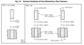
The surface or surfaces of a regular feature of size shall not extend beyond a boundary (envelope) of perfect form at MMC. This boundary is the true geometric form represented by the drawing. No variation in form is permitted if the regular feature of size is produced at its MMC limit of size unless a straightness or flatness tolerance is associated with the size dimension or the Independency symbol is applied


My interpretation is that as long as any measurement taken on the plate falls within .5000/.5006 AND the form of the plate can fit between two theoretical planes that are .5006 apart, then the part is per print. However, most customers don't need that and especially don't want to pay for that even though that is what they are technically calling. It is better practice imo to call a flatness on something like this to open up the tolerance. A .010" flatness for example would override the MMC boundary per Rule #1.
 
Thst would require the thickness to have a feature control frame. This was not stated in the example.
 
Thst would require the thickness to have a feature control frame. This was not stated in the example.

No feature control frame required. Y14.5 calls out a feature of size as any directly toleranced set of opposing planes, diameter, etc. Here's an example from Y14.5 2009 that shows this as well.

y145_form.jpg
 
There is no flatness implied

They sell you shim stock in a roll

There are some things that get implied, you cannot have a highly accurate dimension without a particular surface finish for instance, but flatness is not one of them

Parallelism would be assumed to some extent, because you can only get so far out of parallel with a 6 tenths callout

For all you know the the part could have a half inch of warp and be totally functional

Has to be called out

This is how you lose a quote when you start assuming things that simply are not on the drawing.
 
Size dimension

So you put a piece of thick wall tube in a lathe. You turn the outside, lets say it's 8" dia. and it's round and parallel. Using a ball end mic. to measure with you bore the i.d. until the radial thickness is .5003. Cut a piece out of that tube, at any point it is .5003 thick. Does it get past inspection?


Back
Top