What's new
What's new

Three plate method for true square surfaces?

partsproduction

Titanium
Joined
Aug 22, 2011
Location
Oregon coast
I guess the title says it all. Given three cast angle plates and a true plane such as a surface plate, could the 90 degree accuracy equal the perpendicularity of true 90 degrees that the surface plate has in flatness using the same sequences as in scraping three plates?

The concept takes flatness and adds the 2nd dimension, it seems to me that it would work equally as well. I love the idea of using the three angles and a flat surface to "find" true 90 in the absence of any other testing method.
 
I don't remember where I read it but I came upon a nice write up once of someone doing just that alternating between the angle plates and a surface plate to speed up the process. In practice: A to B, A to plate, B to C, B to plate, C to A, C to plate, rinse and repeat. Never done it but like I said it's out there somewhere. I believe the three plate method is the traditional way for truing angle plates. Whenever I need absolute squareness I use reversal methods. A very interesting concept in metrology, which can be applied to much more than squareness.
Chris German
 
You can create a near perfect angle plate from referencing it's self.
With the base scraped and level, the two L shaped ends can be scraped simultaneously while checking their parallelism and consistency of angle. If the two ends are parallel and a squareness checker identifies them to to have the same angle, you can then scrape the front while referencing the delta of the sides.
All things considered there is a loss in accuracy as reading error of all stages is accumulated on to the front.
See my other post about the frame level. By ensuring that all sides are parallel and the faces of the same angle from one another, I can determine it to be square with in a few tenths of a thou.

http://www.practicalmachinist.com/v...inspection/scraping-cheap-frame-level-303092/
 
I made a set of three angle plates using the three plate method. You do have to alternate between comparing the plates to each other and keeping them flat according to the surface plate, but it works very well.
 
The "Three Plate Metod" will in theory prodice perfect right angles as well as flat surfaces. The most economical path to the theorectically perfect right angles and/or flat surface is not strict rotatoion A to b, B to C, C to A but it will work if more laborious, The system more economical of effort is the "Reduction of Erroros" system best described in Chapter 21 of Charles Porters "Engineering Reminiscences". Porter was a later contemporary of Whitworth who published the technical papers founding the process.

Here is a website listing a number of informational and materials resources including the Whitworth papers, Charles Porter, ect. I regard this compendium as an essentila starting point for anyone interersted in establishing an intellectual background and discussion of prior art for precision scraping.

Hand Scraping (For Precision Surfaces)
 
Not to hijack your post, but I'm going through this right now. :angry:

I sort of suspected that after years in my shop, my inspection equipment is not up to snuff when I planed John Oder's straight edge last year. I came to the conclusion that after planing, despite several straight edges & a couple surface plates here, none were reliable enough to determine actual error. Strictly speaking, this did not affect my agreement with John, since he generously planned to accept whatever result off the planer was better than the SE as received. I had said that if it came off worse than (IIRC) .003" total tolerance, I'd rough scrape the error down a bit before shipping. As it turned out, I detemined that I could not actually measure error in a 5' SE with the (condition of) tools in my shop at the time beyond a guess, and in retrospect thankfully did not try to scrape it. John was gracious enough to take the SE as was. :)

Fast forward to this year, I recently planed a nused 54" bed to put under my 10K and went to scrape it. I went further along than I should have before stopping and addressing the tools. After some careful checking, it turns out my primary 4' SE had a twist in it, my secondary was indeterminate since there was nothing reliable to check against, and my 24 x 36" B & S plate is shaped like a mound, so no using it across the diagonals to check or scrape the SE's.

I only have 2 4-footers (and nothing longer) So have been gradually scraping them in yesterday by checking against each other, and then the ends on a fair 18 x 24" Starrett plate that was new to me from the factory, and on a section of the B & S plate that registers that both SE's are in fact concave when checked to each other and to the plate in that area. What is difficult to assign reliably, is which one is more concave at the moment, but they are trending well together. I do recognize that when I decide they are finished, without 3 full length SE's tpo compare, one will probably be ever so faintly concave, and the other convex. But it is interesting how closely that can be for both, to flat & I think I can determine which is which, applying them to the lathe bed as the 3rd reference.

I would advise strongly that you be absolutely certain your plate is flat in the area used to work your angles, or they will not be a true 90°. Further, if you have not done this before, tiny amounts of marking medium with throw the angle as you get down to final resolution. Try this: clean the plate and the work scrupulously. See how 2 squares hit. Now take a new magic marker and draw a line on the bottom at one end, of one of your squares. This will essentially create a shim. Now see how they hit. (be sure to clean any wet marker off the plate, or it will locally throw anything that passes over it later.)

Blue works the same way: let one end thin more than the other or ride thew work while checking over an area where the die is partial, and the indication will be off. By the time the angles are being final proven, there should be enough die on the plate to faintly register on the work, but not enough to feel with your hands as a drag. Of course this would be for an inspection angle; if the angles are going to be used on a mill, they don't have to be that final degree of match since use will quickly mar/wear them.

smt
 
Thanks for the scraping treatise Forrest, I had seen that before but forgotten it. Now it is bookmarked and I'm determined to read it through carefully.
 
Stephen, your post amazed me with several new concepts, the notion that magic marker would effect an angle plates perpendicularity is astounding to me. Also, I would have assumed some very slight and very very slow unwinding and/or distortion of cast SE's over time, but would not have thought the error would be enough to effect .003" in 5 feet.
I have been checking my CI straight edges with a grade A 2 X 48" granite SE, so, am I now to withdraw the confidence I held in that as well?

.003" was the unilateral tolerance I thought I could predict hitting with my planer in the 5' length based on previous experience and various checks over time. This was based on (at time of erection) indicating a 4' SE on the table, an 8' SE on edge (which had slight known error and was sold a year of so ago since I could no longer lift it effectively by myself) and also more recently the marks on the freshly planed table from spotting with a 4' SE.

When my two 4' SE's were placed face to face, only the ends hit. When tried on my B & S 24 x 36 surface plate, however, both could be spun like a top about equally, especially across the diagonals. With a piece of aluminum foil (.001" thick) between them, in the middle, the foil could not be pulled. My conclusion was the surface plate is shaped like a mound. At least one SE was hollow. From prints on the lathe bed (54") being scraped, and against each other. I determined both were hollow. The lathe (SB 10K) is too narrow to use as a 3rd member for scraping, but serves as a reasonable comparison between the other 2.

My Starrett pink 18 x 24 was new to me, always covered and always treated well. However, as a Grade B plate, it's unilateral tolerance when new need only be 3 tenths. As seen with the foil test between the SE's, that could be more than the SE tolerance. But between the known bad 24 x 36 plate and the 18 x 24 combined with rotating the SE's against each other, then the ends against the plates to control twist, and against the lathe bed as another arbitor, I got them close enough for my current purposes.

I'd kind of like to get a 3rd 4' SE so they could be kept up in the shop. But practically, first order of business is probably to explore the resurfacing options for the larger surface plate.

That, and get some actual work done and income coming.....:rolleyes5:

:)
smt
 
I had purchased a very cheap Chinese no name box level, specified to within .0002" per 10" length, for under $100. Actually the vial seems to be very good for the money, but the 2" wide cast iron edges were surface ground, which I knew going in. They had made some compounded flaking that makes marks that look like a bird in flight, which looks like were made by carefully cross flowering exactly on top of the first pass at a 90 degree angle, not unpleasant but not needed either, as these flats would never wring to anything.

I went to use it on my Havir Shape-Rite project, which had previously been scraped and flowered on both sets of vertical surfaces. The rams flat ways I knew to be way out of perpendicular so I had milled it after much painstaking setup. When I bolted the shaper body to the welded fixture that was bolted to the concrete floor (Made just for scraping these ways) the box level said the ram ways were .0035" high at the front, HUH? How could that be? So, I adjusted the welded frame so the vertical ways were straight up and down, which put the front of those flat ways .0035" high at the front and started to scrape. Being amazingly lazy I made a pass just to rough it up all over and called it a night.
I then asked my brother if he would like to come over and help me scrape it in, as his presence seems to galvanize me into opposing my natural laziness, and when he came over the next Saturday I told him we should check the squareness of the box level before we got started.
The result was that we spent the whole day scraping the level instead of the shaper! It had,,you guessed it!, a parallelism out of square of .0026" in 10". So most of what I thought was wrong with my careful mill job was the level.

Moral, check the standards before starting, as you said Stephen. I don't know if the box level was made that way or if it "unwound" to that, and thinking of that I better check it again before starting to trust it in the future. BTW,some of those pretty surface ground flats sure look bad at the first spotting. It's hard to believe they would use clapped out surface grinders to grind test equipment.
 
I have been scraping a 3ft Brown & Sharpe SE in preparation for scraping the bed of a South Bend 10K, and Stephen's posts above got me to thinking about my own surface plate - a Chinese 18x24x3 grade "A" from Shars. I got it four years ago just before taking one of Richard's workshops down in Oakland CA. It has had only occasional use since I am a hobby machinist with several other time consuming hobbies. I've used it while scraping a 18" SE, a 32" SE (one of Stephen's castings), a slotted cross slide for my 9" south bend lathe from MLA, and now the 3ft Brown & Sharp SE.

Although I wouldn't think the above is enough to wear the plate significantly, I really don't know how quickly granite SPs wear, or whether the original certification as grade "A" was trustworthy to begin with. So this week I took the SP down Cal-Cert in Portland to be calibrated and lapped if needed to grade "A". I was quoted $15/SF for calibration and $125/hr for lapping. I saved the $100 site visit fee by dropping off and picking up.

According to Cal-Cert, before lapping the SP had a flatness reading of 0.000300 and a repeatability reading (explained to me as a measure of "ripple") of 0.000220, which did not meet grade "B" specs. After 1/2 hour lapping, the readings were 0.000150 flatness and 0.000050 repeatability, meeting grade "A" specs. Total costs was $107.50.
 
DS, Was the plate on 3 points? I have seen where those Chinese plates come and they are not marked where to put the 3 points. Did yours or did you put your own 3 points under the plate? Thanks for the Info on the price of the lapping. I am glad your teaching :-) How about some pictures. Rich
 
Richard, Yes, I had it balanced on three 2x2x1/4 inch wood pads, each about 5" in from the edge. Interestingly, the technician who did the lapping commented that my plate might be a little bendy to lap to an "A" certification. I suppose that I could support it more evenly on four points if two of them were on a beam that rested on a single point at its center. For now I'll just stick to the three points.

The technician also said that the deviation from flat was a shallow hollow in the center of the plate which was 3 tenths initially and was 1.5 tenths when he stopped. My thought is that I'll try to spread my spotting around the outside of the plate when I'm working on smaller items like angle plates or the cross-slided and compound of this 10K lathe - kind of like trying to keep your Arkansas sharpening stone flat by using the whole surface when sharpening woodworking chisels or plane blades rather than just the center.

Can you comment on the rate of wear on surface plates? I would think that the spotting medium (Canode Blue in my case) would tend to lubricate the plate somewhat, although if one rubs the blued work on an unblued section of the plate afterwards to get the shiny high spots, I suspect that would tend to wear more quickly.
 
My understanding is that the technician lapped it with the granite surface plate on top since the lapping plate was about the same size as the surface plate but significantly heavier.
 
My understanding is that the technician lapped it with the granite surface plate on top since the lapping plate was about the same size as the surface plate but significantly heavier.

Ah that sounds interesting. Till now ive only seen a surface plate lapped from the top.
77984d1370163346-diy-surface-plate-lapping-dry-rub-1.jpg

Maybe thats why the tech made the 'too bendy' comment. Ie when the plate is flipped back upright and mounted, youve got gravity pulling it the opposite way as when it was being lapped.
Guess the first port of call as to mounting positions is to ask the tech what they advise, used when they measured it. If thats not possible for whatever reason then mounting at airy points would be a good bet, 25% ish in from the edges iirc, to minimise the possibility of bending.

blurb.jpg

page 5
http://www.vermontphotonics.com/FlatnessSpec.pdf

Second what Richard said, would be great if you have any pictures.
 
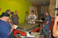
In the Minnetonka MN class we had a few years ago we had a professional granite plate lapper come and show us how he lapped a plate. It was real interesting. The plate was a Grade A and he made it a grade AA.
DSC_2759.jpgDSC_2780.jpgDSC_2755.jpgDSC_2758.jpg


Back
Top