What's new
What's new

ToolMaster feed motor removal

Froneck

Titanium
Joined
Dec 4, 2010
Location
McClure, PA 17059
My ToolMaster feed motor died I think. Was taking a light cut with fly cutter and lost power. RPC motor was still running 5HP lathe motor started with no problem so I looked at ToolMaster controls. OL was tripped which dropped out power contactor. Reset OL, contactor operated but when I went around to front of machine it dropped out again. Reset OL, turned feed motor switch off, contactor energized and spindle motor operated.
Having the repair manual I see the feed motor is held on with 4 screws and keyed shaft slides into worm gear. Removed the 4 screws and with aluminum bar and hammer separated the motor from the gear box about 1/8". Inserted 2 pry bars opposite each other and motor moved to about 5/16 to 3/8" but will not move any more.
Anyone ever remove X feed motor from a Toolmaster Mill?
 
Hasn't anyone ever removed the feed motor of a Cincinnati ToolMaster vert mill?? I do use a pair of pry bars but worried I might crack the flange. Motor as a flange about 8" diameter, 4 unthreaded holes connecting it to the same size flange that is threaded. As I mentioned motor did move about 5/16" but stopped.
 
I have -- or rather I've removed the entire power feed, not just the motor. It's been a minute, but the manual instructions were pretty good as I recall. Various shafts and things are pinned, and there's gear change forks in there like a manual transmission on a car. So I'd say you're wise to be cautious.
 
I do have the repair manual I guess. It's the older type that is complete plus I have the newer manual that is Plastic bound and has operating instruction but nothing on parts or assembly. As per the manual there is nothing holding the motor in. Motor keyed shaft simply slides into the worm gear shaft. 4 socket head cap screws hold the motor on the gear box. Over the years I too have removed the gear box and internal components on other ToolMasters of the same vintage but that has been quite a while ago. I'll again read the removal instructions if there is some, maybe I missed something.
 
I 've never had one of these apart.
in case you haven't seen them ,
There are some repair manuals on Vintage Machinery .
Cincinnati Milling Machine Co. (Milacron) - Publication Reprints | VintageMachinery.org
This is for one model
http://www.vintagemachinery.org/pubs/2097/15219.pdf
It shows a feed motor and gear box assembly on page 39
with a nylon bushing that goes on the motor shaft and Perhaps acts like a coupling .
If yours is the same perhaps there is some wear in there that is preventing the key from sliding out or something.
There is another Toolmaster manual farther down on the list too .
Cincinnati Milling Machine Co. (Milacron) - Publication Reprints - Cincinnati MT Toolmaster service manual & parts list | VintageMachinery.org
Jim
 
Hey, thanks for posting that link. I have scanned copies of an original, and I've been e-mailing them out over the years to folks that request them. Nice to have a link I can point them to, as mine take a few different emails to send due to size.
 
I do have exact manual in the link 2097/15219.pdf. Both are No. M-2318 and Dated 6/63. Mill I have is the same as on the cover.
Motor is on page 74 not 39. Removal instructions Para. 2 on page 21
My Motor is slightly different in that it has no cover and looks like a short motor (Pancake) The 4 mounting screws #139B are not covered but there is a small cover in the back to prevent chips from getting in the motor, I removed the cover, motor shaft and ball bearing are visible. Motor does not resemble Fig.24 on page 24. It is like a typical motor with rotor inside the housing.
Tapping on the round head screws (as per instructions) is the same as tapping on the motor housing or the flange since those screws are threaded into the flange. The motor flange and Gearbox flange are separated at this time about 5/16". But tapping or prying the motor will not move any additional amount.
 
I'm a bit confused. First, you note that the feed motor "has no cover and looks like a short motor (Pancake)", which suggests that it is the original axial air gap motor, but perhaps without the original cover? But then you state that the "Motor does not resemble Fig.24 on page 24", which is an illustration of the original axial air gap ("pancake") motor.

Can you post some photos of the motor and gear box?

What is the serial number of your Toolmaster?

What voltage are you supplying to the machine, and what are the numbers on the heaters for the powerfeed motor? What are the amperage ratings on the motor nameplate for the voltage(s) it is rated to operate with? Have you performed any checks on the motor before attempting to remove it, i.e. verified that the leads do (or do not) have resistance to ground? How many leads come out of the motor?

When the instructions state to tap "on the round head screws around motor," they refer to the slotted round head screws that hold the sheet metal cover (previously removed in the same step 2) onto the axial air gap motor, not the screws that hold the motor onto the mounting flange on the back of the gearbox housing.

I've had my Toolmaster 1-B powerfeed gearbox completely apart (there's a discussion and photos on here somewhere), and had the axial motor re-wound (a previous owner had it re-wound, but only brought out the 440v leads...), and the shaft just slides into the counterbore in the end of the worm drive shaft (174B in the M-2318 illustration). Mine is old enough that it did not have the nylon sleeve, so that must have been a later design change to allow for alignment issues between the shaft and motor.

If it were my Toolmaster (and once I'd verified the electrical items above), I'd remove the front cover of the gearbox, and watch what is happening to the worm drive shaft 174B as the motor is moved back and forth for what little bit of travel you can get without forcing it. It could be that the motor shaft and/or Woodruff key is too tight in the counterbore of the drive shaft 174B, and binding. If so, you might be able to remove the circlip (176B) and push the shaft and motor out of the housing, assuming that the shaft is not bound up on the inner races of bearings 143B and 175B. With only 5/16" movement of the motor, you won't be able to get circlip pliers onto 141B to allow the rear bearing 143B to come out of the housing with the shaft. You may have to remove circlip 141B once it's accessible, since the smaller front bearing 175B is not held in the housing and may want to come out with the shaft, i.e. it floats in the housing bore, probably to allow for expansion. Here's a photo showing the smooth bore for the small bearing in the upper left.
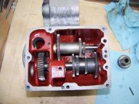
100_1022.jpg
 
Last edited:
I will make photo tomorrow. I'm not sure how a pancake motor is made, My motor is about 6" long. No it does not look like the Fig. 24 but does resemble a typical old motor with cast iron end caps. It is open on one side with a small cover to prevent chips from getting in the motor. Machine name plate has it set-up for 240VAC, I have been running the machine for over 20 years and it has been working fine. I have never tripped an OL! When I looked at the drawing and seen the motor was held on the gear box with 4 socket head cap screws, keyed shaft slides into worm gear I though I could easily remove the motor and test it. I have owned quite a few ToolMasters and have taken the gear box apart but don't remember ever having problem removing the motor. However this ToolMaster was in excellent condition when I got it so I've never needed to fix anything.
 
The SN of the ToolMaster is 6J4C5K-11
I'm wondering if some time it it's life time there was a crash. Or maybe the key is wearing down and the shaft turned wedging the key in what is probably a hardened worm spindle. The end view of the motor shows 2 threaded holes for the 2 screws that hold the cover plate on. Cover plate has opening facing down so chips don't get into motor. Clean area on the top shows size of the cove plate, it does not cover the 4 round head screws holding the motor together. If I were to remove the 4 round head screws I can remove the end plate and the field section and put a strap wrench on the rotor and turn is backwards and align the key. On the other hand it might have 1/2 the key in each slot. On the right side of the top view you can see a slight projection, there is another on the opposite side. When I removed the 4 mounting screws I used an aluminum bar and tapped it with a hammer. It move about 1/8". Now it's opened about 3/8" with pressure from pry bars about 18" long But will not move any more. (seems like it's not moving but may be moving very little) Paint on the motor is exactly the same color as the machine, machine has never been repainted. It is still original paint.
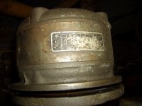
Motor photos
CIMG2088.jpgCIMG2089.jpg
 
Looks like your Toolmaster was made in 1961.

Agreed, that motor does not appear to be an axial air gap as in the factory manual. Cincinnati might have changed motor suppliers (I believe that all of the axial air gaps were supplied by Fairbanks-Morse, but I can't see any manufacturer info in the photo you posted of the nameplate).

Unless they changed something when they went to a different motor, I don't see any reason why it shouldn't just slide out of the end of the worm drive shaft. The different Toolmaster manuals show no change to the drive shaft part number, except for when the nylon sleeve was added.

Here are some photos from the feed motor on my 1-B Toolmaster (vintage 1956):

100_0425.jpg
As purchased. The cover on the feed motor was installed upside down; the electrical leads should be at the bottom.

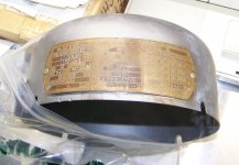
100_0852.jpg
The dataplate and cover from the feedmotor.

100_0501.jpg
The backside of the gearbox housing once the motor is removed. The only connection between the motor shaft and the worm drive shaft in the gearbox is the Hi-Pro key.

I suspect that you're going to have to pull the worm drive shaft as a piece with the motor until you can get them apart off of the machine.
 
Yeah I 1961 vintage, I also checked my SN book. Having about a 3/8" gap I can see the shaft. There is no Nylon bushing. I'll bet the key sheared maybe 1/2 way and is jammed in the worm shaft. Problem removing the worm shaft is the snap ring holding it in.
I'll keep trying but don't want to put too much pressure on that trumpet like flange that connects the motor to the gear box. I don't want to crack it.
 
You're right - I had forgotten about the shoulder on the worm drive shaft that prevents it from sliding out through the rear bearing inner race.
 
Could you get a slim pickle fork down into the gap between the motor base and the gearbox housing flange? Something that would just be wide enough to straddle the motor shaft, could wedge between the end of the worm gear drive shaft and the motor, and could force the motor shaft out of the bore of the worm drive shaft? Might have to make a tool to do this job...
 
Mtg. screw holes not tapped completely thru, couldn't get screw to start from back side. Used taper tap to maybe clean the last thread but other 2 holes the distance is short so tap would not fit. tried to get 1/4-20 screw started but no luck! Though I could cut a flute in a "Allen" cap screw and use it to open the back side but couldn't so I looked in my broken tap junk pile found a 1/4-20, put it in my tap grinder and put short taper threads, probably only had 1 full thread. Other 2 holes now accepted hex head cap screws inserted from the rear to form jack screws. Pressure on wrench was surprisingly light so I wasn't worried about cracking the casting! Easily moved motor 5/8" opening. Inserted 5/8" blocks to extend jack screw length since all I had was screws with 1" threads. Again motor easily moved, reached screw thread length max. Tried bars but pry bars they didn't seem to work so I had some delrin blocks from a delrin job I had and used them to extend jack screws. Motor was almost completely out, put support under motor and pry bar finished the job. Powered motor and it ran! Not much of a worm gear shaft available but with finger tips was able to turn it so engaged feed and was able to move table in the finest feed (feed I was using when I had problem) Looked at wired near the entry into motor, seen outer covering of coiled flex wire (Telephone hand set like wire) cracked away and wire insulation crumbled away too. That must have been the problem! But I was right, key worn and jammed in shaft opening. Was late since I started the disassembly after completing my work for the day I didn't measure shaft or hole diameter. Someone made a thin split bushing for the motor. Motor shaft looks to be 1/2" and shaft opening 5/8". Today I'll measure it! Not changing the key height there is not much key available. Motor sounds like it can use new bearings so I'll replace them.


Back
Top