Cutler Hammer Remote Station Wiring, Sylvania Reversing Starter
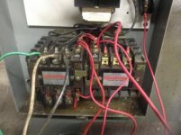
I also see improper hookup to the remote PB station.
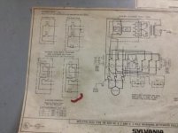
Clues: The diagram in the cover is marked red for the 5 contact block remote station ( the diagram is illegible from my end) and it appears that this is also the switch you have, with 5 contacts. Is this the diagram you used for hookup?
When I lookup the diagram for your starter, and a fwd/rev/stop control station, the diagram shows only 3 contact blocks required. As in the upper right control station drawing on your schematic. Yours has 5 contacts, and it appears that 4 of them are being used. The other issue is your diagram is shown for a Sylvania remote station and you are using a Cutler Hammer remote station. There may be differences of terminal layouts between brands.
It appears to be the case to me, again I can't really see the contact arrangement of the CH contact blocks from the photo provided. The top two contacts appear to have a vertical arrangement while the middle two appear to cris cross, while the bottom stop contact is a horizontal arrangement.
The drawing on the starter for the OEM control station shows all 3 contacts in a horizontal contact arrangement.
You may need to transpose the remote station wiring configuration and only use 3 contacts as shown in the Sylvania OEM drawing.
Link to the starter manual drawing,Pg 53 show the reversing starter and remote station. Pg 54 shows a 5 contact remote, but shown for use on a 2 speed starter.
EDIT/CORRECTION: Pg 57 shows the reversing starter with a 5 contact remote. The additional contacts are shown for remote station electrical interlocking, in case the starter lacks mechanical interlocking. But still the drawing shows all horizontal contact arrangement.
https://www.google.com/url?sa=t&rct=j&q=&esrc=s&source=web&cd=1&cad=rja&uact=8&ved=0ahUKEwi414n6tYrLAhUE5WMKHUy2As0QFggcMAA&url=http%3A%2F%2Fwww.danaherspecialtyproducts.com%2FuploadedFiles%2FSiteroot%2FJoslyn_Clark%2FProducts_and_Solutions%2FNEMA%2520Control%2520-%2520Heavy%2520Duty%2520(Section%2520B).pdf&usg=AFQjCNEVeoqI2Vs6wsoJlD-lG36e8RytzA&bvm=bv.114733917,d.cGc
And here's a current CH remote station similar to yours, but it doesn't show the 5 contact model, pg 18. It show a horizontal contact arrangement on all 3 contacts. I think your switch is a slightly different model with more contacts and a different layout.
It's probably still suitable for use but the contacts and wiring would need to be interpolated between the diagrams.
http://www.eaton.com/ecm/groups/public/@pub/@electrical/documents/content/vol07_tab01.pdf
SAF Ω