What's new
What's new

Very early Monarch 10ee

So it looks like the Baldor VFD and Baldor motor are both rated for 7.5 hp. I guess that means that the VFD cannot be derated? CDCDBB63-9A23-4A97-AF02-5FEC4A8A56A5.jpegSo using single phase power with this set up will not work? Can I leave the VFD in place and use a rotary phase converter? Or should I just replace the VFD with a larger one?231BC27A-43A0-4C82-9327-E6DDC0238967.jpeg737798D0-8839-4409-8238-B6D56C9B2A2E.jpeg
 
Very nice early machine! I especially like all the early features that are in amazingly good condition. By 1940, many of these were eliminated, and in 1941 more were eliminated. These are the ones I noticed:

The feed/thread control dial and handle
The pointer on the cross slide for the compound angle
The domed covers for adjusting the feed clutches
The knob on the apron for selecting fwd feed / threading /rev feed

It also has the early design taper attachment which changed in 1941 to the model that was used for the rest of 10EE production.

And the gearbox has the chrome plated iron knobs and round dial. In 1941 these changed to zinc or aluminum.

And of course, it has the original castings, like the headstock covers and the base with the right hand extension, all of which changed in 1941 when the mg came out.

I think that if you get a copy of the 1939 sales brochure, which is posted on the forum, you will see all those features.

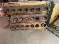
Inside the door in the center of the lathe should be a 5C collet rack, which also was eliminated starting in 1941. That rack came in two or three varieties: most common was the single layer rack which holds a full set graduated by 1/32”. The double rack would hold a full set graduated by 1/64”. I think we have seen one early lathe with a third layer, so it held squares and hexes in addition to 64ths. Pretty amazing.

If it came with any accessories or the optional Monarch tool cabinet, please post some photos. The early clamshell indicators were made from iron, and are quite hard to find.

I think this will be a spectacular machine once it gets cleaned up, so best of luck with it!
Here is the collet rack:D51A88B5-33C4-46DB-BDDE-52D7EC198BD0.jpegA6220817-CA19-4C03-89A3-79287BB545E8.jpeg
 
With that single belt, there is no way that you can get 7.5HP into the lathe. I have some 10HP VFD'd that derate to 5HP on single phase. Yours is likely similar. You should try your VFD on single phase because it will likely provide as much power as that belt can handle.

Gates has a very nice design guide for belts here:
That should give you an idea of the limits of your current setup.
 
You need to look at the lowest speed that the motor will be running and size your belts accordingly. A single belt might be enough at top speed, but not as the motor slows down. Belts transmit force, not power. As the speed goes down, the force has to increase to maintain a certain power level.
 
I'd run the existing set up and see what you have and how precisely the lathe turns. The motor pulley is small vs the spindle pulley so top speed at 60 hz is likely under 1000 rpm and at 10 hz the hp is under 1.5 and in the 100-150 rpm range. Learning the existing limitations will give you better info regarding a pulley swap and perhaps a vfd swap.

With no back gear, a vector duty motor would be a better choice but some experience on the machine will tell you how to compensate. Some early 10ee had a clutch on the spindle so braking is less an issue for the vfd, and HSS tooling or even inserts can reduce the need for rpm over 2000 o aluminum so a more narrow speed range isn't a deal breaker. Two or three groove pulleys are cheap on ebay and BX belts are also so swapping those doesn't break the bank. Just check that the spindle pulley is a standard multibelt. My CVA pulley has a nonstandard width between grooves which complicated any swapping. I believe monarch used a standard design but verify.

Dave
 
I'd run the existing set up and see what you have and how precisely the lathe turns. ...
Agree.

... Some early 10ee had a clutch on the spindle ...
Not that I'm aware of. First generation Sundstrand drive machines, like this one, had a lever so you could disengage the dog clutch for the threading gears, but they quickly deleted that option. Engaging the clutch with the spindle turning was a very bad idea. But the dog clutch itself is no different than late model 10EEs. The spindle itself is directly driven by the upper pulley with no clutch.
 
they must have used a flame hardened hinge pin :p (jk)
pretty impressive it doesn't seem sprung after all this time.
 
So it looks like the Baldor VFD and Baldor motor are both rated for 7.5 hp. I guess that means that the VFD cannot be derated? View attachment 386262So using single phase power with this set up will not work? Can I leave the VFD in place and use a rotary phase converter? Or should I just replace the VFD with a larger one?View attachment 386263View attachment 386264
The VFD will if "at or above" the 7.5 HP of the motor will provide what's needed. A lot of guys actually use double the VFD to motor, which to me a is a bit overkill. I run 10 HP VFD's on my 7.5 hp motors with beautiful results. I also use the original double belt set up which I think helps transmit power a bit better especially at lower rpms, so you may want to consider a different pulley set up. I also just realized that you don't have the two speed gear box on yours, so that kind of accounts for the smaller drive pulley. You'll need to play with the math to determine where you ant your power and top speed to be at. A good rule of thumb is 30 to 90 HZ range, So you can half your normal speed at 60HZ and add 50% on top. Playing with the pulley sizes in that range will help you determine what speed range you'll have and where you'll have the most power. Torque will be constant, but lack of RPMs can cause bogging even with good torque. HP= torgue X RPM / 5252...
 
My mistake on the spindle clutch. I thought CVA early versions were a direct copy of the 10ee but the clutch on the CVA is on the gearbox which the 10ee didn't need. Dave
 
The VFD will if "at or above" the 7.5 HP of the motor will provide what's needed. A lot of guys actually use double the VFD to motor, which to me a is a bit overkill. I run 10 HP VFD's on my 7.5 hp motors with beautiful results. I also use the original double belt set up which I think helps transmit power a bit better especially at lower rpms, so you may want to consider a different pulley set up. I also just realized that you don't have the two speed gear box on yours, so that kind of accounts for the smaller drive pulley. You'll need to play with the math to determine where you ant your power and top speed to be at. A good rule of thumb is 30 to 90 HZ range, So you can half your normal speed at 60HZ and add 50% on top. Playing with the pulley sizes in that range will help you determine what speed range you'll have and where you'll have the most power. Torque will be constant, but lack of RPMs can cause bogging even with good torque. HP= torgue X RPM / 5252...
Thank you. I might just try keeping the existing VFD and see if it performs fine off single phase power.
 
Here is the collet rack:View attachment 386266

That makes four options for the early collet rack: yours has space for a set of 5C by 1/16"

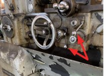
I noticed that currently you have both the Z and X feeds engaged. Unlike the later 10EEs, there is no interlock to prevent engaging both at the same time, so be careful.

Also, an other photo shows the feed belt. It is running on the wrong side of the idler pulley, just thought you would want to know.
I’m new to lathes altogether so forgive my ignorance, but how can you tell that both z and x feeds are engaged?
The feed belt is the frayed yellow one I assume?
 
I’m new to lathes altogether so forgive my ignorance, but how can you tell that both z and x feeds are engaged?
The feed belt is the frayed yellow one I assume?
Yes, the feed belt is the yellow one.

Both the carriage and cross slide feed levers are engaged at the same time (pointing down). They would be pointing straight out towards the operator if not engaged. You should only have one or the other engaged at a time. I thought it odd that my '42 10EE also allows this to happen. Out of curiosity, does anyone know when they started installing interlocks to prevent this?

D51A88B5-33C4-46DB-BDDE-52D7EC198BD0.jpeg
 
Yes I think so. Here is a pic. View attachment 386302
Yes, that appears to be an original V-belt drive pulley and the belt idler looks original as well. The frayed yellow belt is what drives the apron feed section of the quick-change gearbox. Whenever the spindle is turning, the larger pulley on the bottom will be turning, but there is a clutch internal to the gearbox that selects either it or the gears visible in the back (called the "end gears") to drive the gearbox. The gears are only driven when the control on the front of the headstock is to either left or right threading. You could change the pulley on the motor and have dual V-belts.
 
Both the carriage and cross slide feed levers are engaged at the same time (pointing down). They would be pointing straight out towards the operator if not engaged. You should only have one or the other engaged at a time. I thought it odd that my '42 10EE also allows this to happen. Out of curiosity, does anyone know when they started installing interlocks to prevent this?

There is no interlock between the carriage and cross slide feeds, they can both be engaged. So far as I know the interlock is only between the half-nuts and carriage feed (and maybe the cross slide feed, never checked that).
 
Mine has v belts from motor to fluid pump, and flat belt from the hydraulic motor to the spindle.
Interesting. I knew that flat belt drive was an option with MG machines, but yours is the first Sundstrand that I've heard of one with a flat belt. My 1943 piggyback exciter 10EE with a 4000 RPM spindle came from the factory with a flat belt drive as well.

Can you post some photos?
 
There is no interlock between the carriage and cross slide feeds, they can both be engaged. So far as I know the interlock is only between the half-nuts and carriage feed (and maybe the cross slide feed, never checked that).
Agree. There is nothing to prevent you from engaging both carriage- and cross-feeds at the same time. In theory, you could use that "feature" to cut a taper. I once figured out the angle, but I've since forgotten.
 
Last edited:


Back
Top