What's new
What's new

VN16 Rebuild

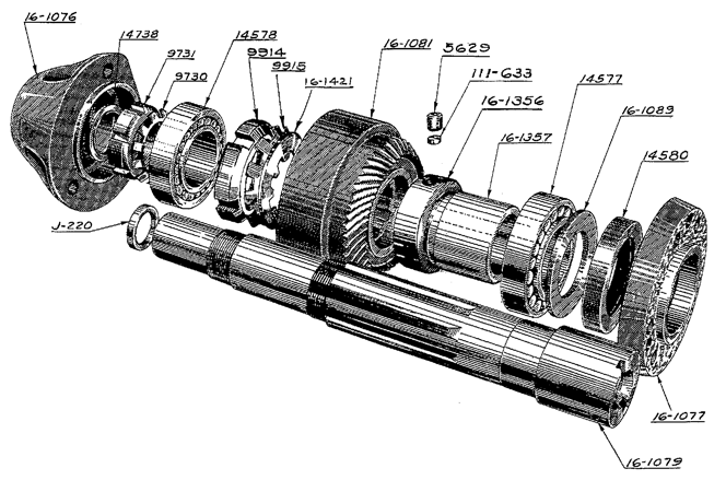
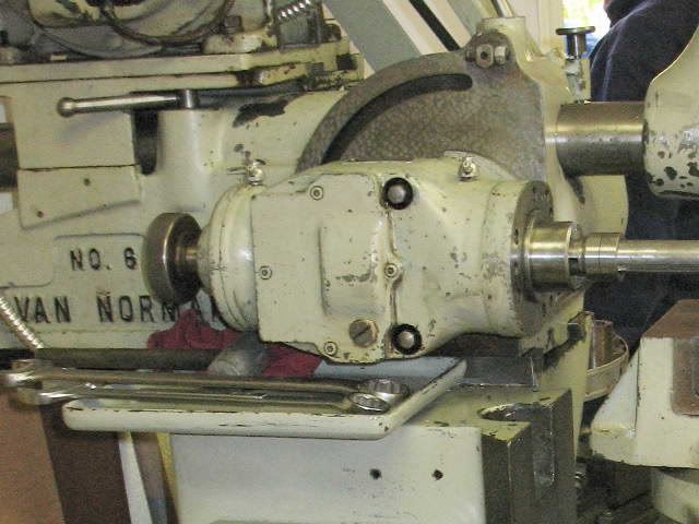
" ...If you have an older manual, I can send you some scans of the pages form a No. 12 manual that show the "new" cutter-head and gearbox. What's interesting is that the "new" No. 12 manual actually shows the configuration of the spindle that I have. My No. 16 manual shows a different spacer between the front bearing and the bevel gear. I have another No. 12 manual that shows a gearbox with ball bearings (instead of the tapered roller bearings) and a very elaborate double screw-in cover for preloading the bearings...."


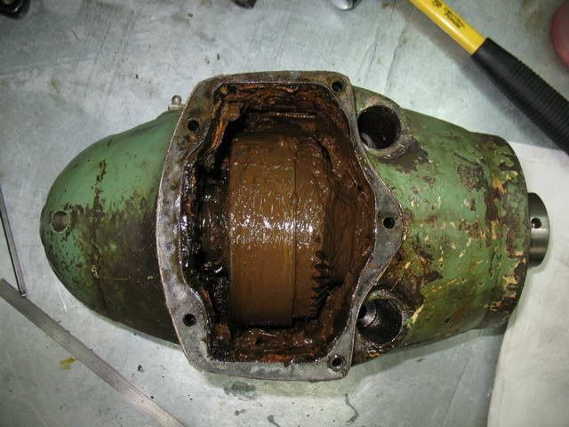
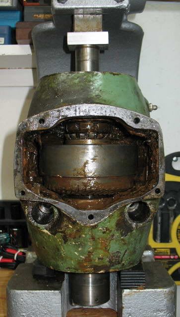
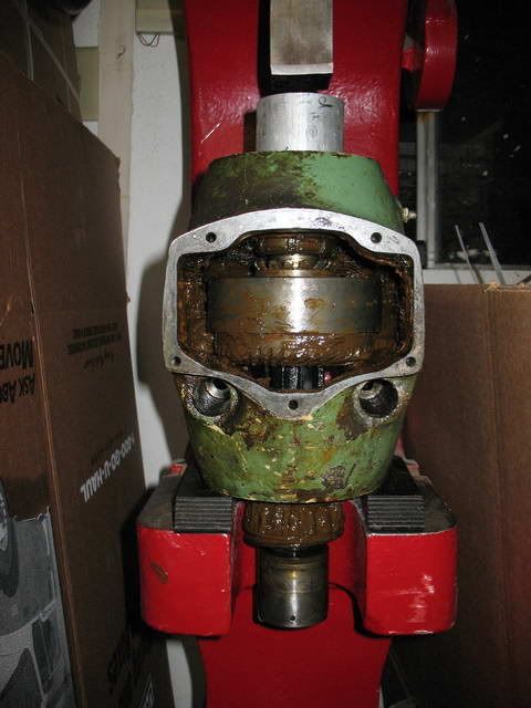
No Thanks as I have found a more recent manual.....I think I'm glad my machine never had a coolant pump on it judging from the "baby POO" that I'm seeing....YUK!

I recently drained and refilled my head and gear box and it was nice and clean.....I'll leave her be!.....keep going though I'm loving the view from here! 8-)

Dave
 
Removing the Gearbox Output Shaft

Since the bearings were obviously shot, the right bearing’s outer race was removed by tapping on the end of the left end of the shaft with a brass hammer. The amount of force required was minimal. However, this might not be the best method if one were planning to reuse the bearings. Another approach would be to reinstall the bevel gear and use the bearing separator to pull the left race by using the tapped holes in the separator to jack against the ram until the race is free. Some lengths of ¼-20 all-thread could then be used to mount the cross-bar and threaded shaft from the bearing separator to press out the right side race.

After the right, outer race was removed, the bearing separator was used to remove the inner race:

IMG_7029.jpg


The output shaft, which has an external spline that meshes with the gear cluster, was then removed from the left side of the ram. A slide hammer with a hook-type tip was used to remove the left side outer bearing race. The monolithic, triple gear cluster from the output shaft could not be removed because the other gears and the shifter shafts were in the way; it was left inside the gearbox for the time being.

Cal
 
Removing the Input and Intermediate Shafts

The right ends of the gearbox input and intermediate shafts are threaded to facilitate removal of the shafts and right side bearings. In retrospect it would have been easier to have used a slide hammer to pull the shafts. A length of 7/16-14 all-thread rod and the slider from one of my slide hammers would have done the job nicely. But I elected to use a puller to remove the shaft instead.

IMG_7102.jpg


First of all, let me reiterate, the shafts are internally threaded 7/16-14. Don’t fall into the trap that I did and think that they are 3/8-16. A 3/8-16 bolt will hand thread into the 7/16-14 threaded holes about 4 turns before resistance is felt, but that doesn’t mean it’s the right bolt!

The bolt holes for the side covers are threaded ¼-20. I was concerned that ¼-20 would be too light for the pulling task, so I turned down the ends of some 6” lengths of 3/8-16 alloy steel all-thread rod and threaded it ¼-20. The actual force required to pull the shafts and right bearing was fairly light, so ¼-20 mild steel all-thread would have worked just fine. We used the cross-bar from my bearing separator kit, some washers and a 3/8-16 nut to pull both shafts. Both outer bearings came free without incident.

Since the stack of three gears on the intermediate shaft spans the width of the gearbox, pulling the shaft simultaneously pulled the right side bearing and race out of the side of the ram and pulled the inner race of the left bearing off of the shaft. The shaft, which is externally splined to drive the gears, was then removed from the right side of the ram. Care should be taken to keep the gears from dropping into the bottom of the gearbox as the shaft is removed. Once the shaft is withdrawn, the three gears and the left side inner race and bearing can be removed from the gearbox. The end play of my shaft was so great that the cage of the left bearing had been consumed.

IMG_7107.jpg


The right bearing with race for the input shaft was removed using the same puller setup as before. However, since the triple gear cluster on the input shaft is shorter than the gears on the intermediate shaft, the inner race from the left bearing had to be pulled separately.

IMG_7123.jpg


I hadn’t planned on needing studs for the puller that were longer than 6”. Rather than make up new studs, we elected to install the body of the bearing separator and use a pair of machinist’s jacks to jack the separator and shaft to the right until the race was free. It was nice to have help supporting things, since the gear cluster and the puller want to fall as soon as the race comes free. Once the input shaft was withdrawn from the side of the ram the gear cluster could be lifted out.

IMG_7125.jpg


An alternative approach would be to place blocks between the bearing separator and the ram, flip the nut and washer, and use the nut to pull the shaft, as before.

An interesting feature of the machined holes for the outer bearings is a shallow groove, probably put in with a die grinder, at about 7 O’clock in each hole. The grooves get deeper in the direction of the gearbox. I’m not sure what the function of the groove is, perhaps to let excess oil drain back into the gearbox?

Here’s a question for the brain trust: Assuming that my bearings were still good and I was planning to reuse them, would a slide hammer be an acceptable method of removing the bearings and races?

Cal
 
Removing Tapered Roller Bearings for Reuse?

...
Here’s a question for the brain trust: Assuming that my bearings were still good and I was planning to reuse them, would a slide hammer be an acceptable method of removing the bearings and races?
Nobody has an opinion on this? That's got to be a PM first...

Cal
 
Alright Cal, here's my $.02:

As long as the shock load from the slide hammer is on the race that's being pushed or pulled, I dont think it makes any difference. What you dont want is any kind of force put upon or shocking the rollers, balls, or cages. In other words, if working on the bearing from a shaft, dont drive the outer race, and if doing the bearing from a housing, dont force the inner race.

When I worked for Okuma field service, we routinely removed and installed bearings by driving the bearing race with a hammer and a kind of punch made from soft steel keystock. It worked fine, tapping gently around the race until it was home. What we were warned NOT to do was use a piece of soft metal like aluminum or brass against the races, as these had a tendency to splinter off easily and the little bits would find inevitably their way into the bearing.

And for gosh sakes, dont clean off the bearings and them spin them dry with an air gun like a siren! But then, I know you know that. :-)
 
Slide hammer?

Depends on teh application I would say.

1) better on tapered roller bearings, than radial ball bearings. Those
are pretty tough bearings. It's easy to brinnell ball bearings and ruin them.

2) depends on the use. Spindle bearings that are going to be possibly re-used?
Never in that case. For shaft bearings like these, then a maybe.

3) how tough are they to replace? If they go bad in service, if buried inside the
machine, then avoid the practice. If they can be easily replaced, then that's
a probable yes.

4) how expensive are they? If cheap, then often it's easier to remove the
bearing (or races, if separate tapered roller bearing type) in any way imagineable
up to and including tigging a bead around the inside the outer race to get it to
drop out. Then simply install new.
 
Removing the Input Shaft Shifter Fork

The shifter forks for the input and output shafts each run on a pair of rods supported by the right side of the gearbox. The placement of the shifter forks and rails make it impossible to remove the output shaft gear cluster, so we removed the shifter for the input shaft. What I didn’t realize until we had the rear shifter out is that the rods are supported only on the right end.

The shifter rods are held in place by a setscrew that bears on a flat on the end of the rod. The rod ends are covered by a slightly domed aluminum cap. A pair of Vise-Grip #7LW pliers turned out to be just the tool to grip the rods. A light tap against the pliers helped pop the cap off and the rods were removed without difficulty. (An alternative approach might be to pry against the left end of the rods, working against the inside of the gearbox.) A white paste was found under the cap; perhaps white lead? I’m not sure what the purpose of the paste is.

IMG_7131.jpg


With the rear shifter out of the way it was possible to remove the front gear cluster. It’s heavy and difficult to handle when covered with oil, so we ran a piece of soft iron wire through the center to lift it out without danger of dropping it.


With the gearbox disassembled, we began disassembling the cutter-head. My short term goal is to get numbers off of all of the bearings and seals so that I can start looking for parts.

Cal
 
Thanks for posting this-It is a lot of effort! Hopefully the VN12 I just bought won't look quite so rough inside......!
I'm glad you're enjoying it.

What's the year or serial number of your machine? I'm interested in knowing if it has the "old" style No. 12/6 or the "new" No. 12/16 cutter-head.

Cal
 
Cutter-Head Evolution

As we discovered earlier, the cutter-head on the plain Van Norman No. 16 is the same one used on the later No. 12 millers. An example of the “old” version No. 12 cutter-head can be found on John Kasunich’s website:

VN_12_Horiz.jpg


The same old-style No. 12 cutter-head was used on this No. 6, built in 1940:

IMG_5322.jpg


The manual for the above No. 6 has ‘12-‘ part numbers for it’s cutter-head. This appears to be another example of a new machine (the No. 6 being introduced one year after the No. 12) getting parts from the No. 12.

For lack of a better designation, I’ll refer to the old style cutter-head as No. 12/6, since it was used on the No. 12 and No. 6 millers; similarly, I’ll refer to the new head as the No. 12/16. Internally the No. 12/6 and No. 12/16 cutter-heads are fairly similar. A major difference was the transition from a single keyway for the bevel gear to the use of an internally splined gear. The other major change was how the meshing of the spindle bevel gear to gearbox gear was handled. Over the lifetime of the No. 12 cutter-head a number of different methods of controlling the position of the bevel gear relative to the front spindle bearing were used. I can go into more detail if anyone is interested.

Cal
 
Cal,
The model 12 I just bought has a 1941 date, # 12-6021- old style cutterhead.
The tale has a number 725 stamped in it , in the coolant trough, left side. I do not know if this is supposed to be the same as the machine number or not. I am speculating this machine may have some some parts from other machines, as the bright green paint visible under multiple newer layers on the main casting and gearboxes seems to be missing from the cutterhead.

One sweet thing about years of grease and dirt accumulation-- for coming out of a barn, this machine shows almost no rust.:)
 
Last edited:
ere's a scan of the shifter data plate from the manual. Mine is so battered and faded that I can't really read it:


If you want a new label made up, there is a PM member who will make them for you..

and you can look at the quality of his work here

More homemade metal labels - Woodwork Forums

If you are interested I will PM you the username that he uses here so you can contact him.
 
Removing the Cutter-Head Side Cover and End Caps

I've been busy with other topics and projects and haven't been able to add to this thread for a while, but I've got a few more installments ready to go...

The cutter-head side cover is held on with 5 SHCSs. It came off without incident. The center reservoir was full of more Oobleck. I was surprised to find grease; it should have ISO 68 gear oil. My research on cutter-head lubrication suggested that the special grease Van Norman used for the rear bearing was calcium based. Perhaps that explains the baby-poop brown color?
IMG_7161.jpg


The cutter-head’s rear end cap is held in place with three SHCSs. A few light taps with a brass hammer broke the many layers of paint loose and some light prying had the cover off.
IMG_7162.jpg


The front cap is held in place with 6 SHCSs. The three tapped holes in the cap, used for mounting accessory heads, can be used to jack the cap away from the head casting. The holes in the plate are tapped 3/8-16 and holes in the casting behind are deep enough that none of the bolts at hand had threads long enough to reach the bottom. I used three of the threaded rods from my clamping kit as jacking bolts:
IMG_7171.jpg


The front cap holds grease seal and has a boss, like those for the gearbox side covers, that controls the position of the front bearing outer race.
IMG_7173.jpg


Cal
 
No. 12/16 Spindle Changes

I was surprised to discover that the spindle in my No. 16 cutter-head is different from that shown in the manual, yet matches the parts diagram in one of my No. 12 manuals.

Here’s what the No. 16 manual shows:
VanNormanNo16p12Cutter-HeadSpindle.png


And the No. 12 manual:
VanNormanNo12post-1947p09Cutter-HeadSpindle.png


The main difference between the two spindles is the adjustable spacer that sits in between the gear and the front bearing. Examining the two drawings it is clear that the No. 12 drawing is a revised version of the No. 16 drawing. Note that the lettering of the call-outs for the revised parts is different that the lettering used elsewhere on the drawing. Also the part numbers for all of the manufactured parts of the cutter-head are 16-10XX and appear to have been assigned sequentially; the revised parts are 16-13XX, suggesting they were assigned later than the rest of the assembly.

The change to the spacer was to go from a commercial shaft nut [10019] and lock washer [10200] to a manufactured ring [16-1356] held in place via a setscrew. Not shown on the diagram is a single spanner hole, opposite the setscrew. It’s easy to imagine that the lock washer was difficult to manipulate, sandwiched between the shaft nut and the gear; or perhaps the lock washer didn’t allow for sufficiently fine adjustment of the spacer. Whatever the reason for the change, later versions of the cutter-head (i.e. the 16M/L and the 22M/L) continued to use a manufactured ring and in fact deleted the remaining commercial shaft nuts from the rest of the spindle. The later spindles also incorporate the spacer tube [16-1357] directly into the spindle itself (the spindle is threaded for the front lock ring).

Apparently the No. 12 manual that I have is more recent than my No. 16 manual. If anyone has a No. 16 manual that shows the revised spindle, I would be very interested in seeing it.

Cal
 
Removing the Cutter-Head Spindle

An initial examination of the spindle showed an amazing 3/32” of end play in the bearings! It’s hard to imagine that this much end play is the result of wear alone. Despite the amount of end play, neither the gearbox or spindle bevel gears were visibly worn. The No. 16 brochure states that the spindle gears are hardened, apparently they’re pretty tough. The gear is a massive thing, obviously intended to double as a fly-wheel. It’s about 5” in diameter and 2-1/4” thick.

Spindle bearing pre-load is controlled by a shaft nut with tabbed lock-washer on the rear of the spindle. The washer’s tabs were straightened with a punch and the washer removed using a hook spanner. Very little effort was required to remove the nut and washer.

IMG_7163.jpg


A second shaft nut and tabbed washer is used to hold the position of the rear of the spindle gear. The nut must be removed as the spindle is pressed out of the front of the cutter-head. The washer’s tabs were straightened by prying against the gear and the nut was backed off about ¼” by using a punch against the shaft washer’s castellations. The nut moved easily.

Based on the condition of the gearbox bearings, I’m not planning to try to reuse the spindle bearings. So the first attempt to remove the spindle itself was to try to drive it forwards out of the cutter-head by using a block of wood and a dead-blow hammer against the rear end of the spindle. This involves simultaneously driving the spindle through the rear bearing and the gear. The gear is driven by splines on the spindle and should be free to move once the rear shaft nut is backed off. However, as soon as the gear came up against the inside of the cutter-head casting all motion ceased, decades of old lubricants, etc., appeared to have cemented the gear to the splines. The spindle was now free to move 3/16”, indicating that we had moved the spindle forwards through the rear bearing a whopping 3/32”.

We tried to break the gear free by driving against the flange on the front of the gear, using a brass drift. No progress was made. In an effort to check for movement of the gear we elected to back of the spacer collar. Prior to moving the collar we decided that we should document the adjustment of the collar so that it could be restored if necessary. We placed two punch marks on the sleeve, opposite the collar setscrew, and measured the gap between the collar and the shoulder on the sleeve. A gap of 25/64” was measured.

IMG_7189.jpg


After the collar was backed off it was obvious that the gear was still in contact with the spacer, indicating that the gear was stuck in place.

IMG_7191.jpg


The next attempt to remove the spindle was to attempt to press it out using a 3-ton arbor press. The press was insufficient to budge the gear. Even after treating the shaft with Kroil and letting it sit for several days the spindle would not budge.

IMG_7192.jpg


Having exhausted the equipment at hand, further work was delayed until I got time drop by kpotter’s shop. We used his 5 ton arbor press and the spindle surrendered without a fight.

IMG_7282.jpg


The shaft nut had to be backed off periodically until it reached the end of the threads. I found a fair amount of corrosion on the splines of the spindle and the gear. This was no doubt responsible for the gear sticking on the spindle.

Cal
 
Cal, I don't envy your having to clean all that glop and muck out of the machine.
Like you (I'm sure) I do enjoy having a machine that I know is clean and well lubed inside, making the effort worth it.
 
It took me over 4 hours to clean the poo off of the spindle components and out of the cutter-head casting. Fortunately it doesn't smell as bad as it looks. It's clear that no one has cleaned and lubed it in a long, long time. There's a little rust most places where moisture could be trapped between components; nothing that won't clean up with Evapo-Rust.

Cal


Back
Top