What's new
What's new

well new machine died Fanuc 18M Controller, not sure what happened.

If you have found a culprit, always desolder and test out of circuit, then usually replace any that are in parallel as they could have been stressed from that failure. I have had it happen to me to replace one just to see another one fail in 10min. You may also be able to spot some upgrade components of higher voltage rating which can help protect the system. High voltage transients can take out diodes.
Planning on doing that to take it out and test it.
I don’t see anything else for other diodes in the same circuit.
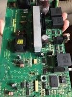
Looks like the previous work done might have been all the small capacitors being replaced as the larger older lxg caps are all brown wrap and newer ones are all blue along with a small transistor that looks to be replaced cleanly.

This diode looks like both diodes in it work both in reverse and have no resistance either direction
As for upgrade components, as in? I’m not super up to date with electronic repairs.

as for tracing the multi layer pcb board, quite challenging here
 
Not sure how deep you want to go here but....it appears the big cap is your main DC filter cap. Some diodes are going to rectify, then the big cap smooths it up but that will be high voltage DC. Those two black boxes with yellow stickers are likely the coils for each voltage. I would first identify the DC input circuit and test that for ripple. If there is ripple, the whole circuit will have problems. that could be a diode or capacitor issue. However, that big cap only runs at 60hz so they are not real prone to failure. The secondary side runs at high frequency so those caps must be low ESR and are subject to failure. If an idiot installs low quality caps there, it might run for a couple yrs or something.

Check the bottom of the caps for leakage. everyone just looks at the top but many of those will give only very subtle signs on the bottom. I usually don't set them down on the board for that reason. So I can see.

Do you know what the input voltage is to this? 208VAC or possibly 24VAC?

Basically, in a nutshell, the components likely to cause issue are the ones on the heat sink, and any capacitor of your choosing. Usually if I identify a cap failure, I mostly do a sweep with new goodies.

EDIT: trying to look at a pic of this thing online and appears there might be a bridge rectifier in there. Rectangular near that big cap. If that is the case, that is likely the main diode pack that works with that big cap. that would be a test point to look for AC ripple. I don't really suspect that bridge as they usually short and blow fuses. That big filter cap might be at issue but if DC is clean, move on.
the huge cap up top is the AC Main cap from the input side where the power first comes in to turn it all on im guessing.
the black boxes yes are my high voltage to lower voltage transformers.
the small brown at the bottom of the heat sink one goes to the 24V output which is connected to the Diode array in question and looks like it pulls from the 24V to the AN7805F which looks to be a 5V voltage regulator
also found some resistors that feed into the mosfet that should be 39K ohm at 2W that are around 20-21 ohms
when running there is no ripple through the oscilloscope even at 1ms
most of the caps are up off the board other then the 2 large ones.
input voltage is 200-230V and looks to have a 24V circuit and a 5V then an internal 15+/- for all the micro controllers with opto couplers that test perfect.
 
were you able to scope the outputs? I realize it is hunting, but you might be able to detect some ripple. Honestly, with the symptoms, I would highly suspect the secondary caps. Likely the ones already replaced.

Usually resistors that start shorting will burn out but just maybe...... It might be worth a test to desolder one side for testing. Usually the resistor will show signs of heat stress. Usually these will need some resistance on the secondary to stay stable.

one thing you could do is meter test the input current to see if it is pulling a lot of power, or at least more than reasonable. Another sneaky thing I use is a FLIR camera to see hotspots on a board. Takes me right to the problem.
 
I can only have a scope on it together in the machine. as i dont have a higher power supply to feed it off the machine. it was clean flat line DC voltage on there.
the resistors look like it comes from the mosfet and back to the controller for it. not completely dead but looks a like it got warm a bit once on one end.
the biggest thing i can only see is the common cathode diode that both diode legs to base test/work both ways.
thermal imaging camera is a good idea also.
 
It sounds like you are a bit limited in what you can do. Because the circuit tries to run, that probably clears the primary mosfets as mosfets typically just blow up, short, go boom, etc. It seems like the circuit is protecting itself. I think getting snapshots of the output in a scope can form some insight for cap failure.

Other culprits could be a shunt resistor (you mentioned). These will be high precision resistors, responsible for giving the current leaving the PSU back to a driver IC. If it is getting a bad value, the unit will protect itself.

Also possible the feedback or flyback circuit is not working, in which it tries to boot up with certain parameters, then realizes there is no feedback, and throttles back. That would go back through the optos and those you can usually diode test in circuit.

You really need to know how much power the PSU is trying to pull. that can indicate a short as opposed to filtering, bad flyback, etc.

Reminder that half of the stuff on that board cannot be accurately tested in circuit without a complete understanding of it, and special equipment and skill. When I test in circuit, I am looking for values that gel with their spec, and I can softly excuse them for a bit. Components that do not test correctly are recorded but not identified as 'bad', just that they may be testing odd in circuit.

However, if you are looking at a FET for instance, you can look at things like the gate for obvious shorts that should not be there. Gate failure is common, which is a dead short, fuse blown, etc. They will also usually take out the gate drive resistor so I look for that. I typically use continuity testing for insight. Behaviors of certain components are consistent. So if you go test across those filter caps and they read a consistent and low resistance, they are on my radar. they should try to charge and you will see changing value with the meter. Not always the best way, but you learn tricks.

At some point, you have to desolder something to figure it out.
Yes I tested the mosfet and it was working correctly as per the specs exactly, its the one in the first picture on the huge heatsink second from left. the Triac to the left of that was good also.

the bad diode array to the right I have ordered as it was zero resistance both ways and across both anodes there is zero resitance .That makes sense why i was recieving half the voltage as the DC is only getting half the AC wave into the 35V DC circuit that drives the 15V communicaton modules and the 5V voltage regulator circuits that all pull from it. The caps were filtering it out id guess, as the DC line had a really flat dc line but had one or 2 tiny blips to it where it went up a few millivolts but that could have been a lead connection.
guessing the circuits are noticing the voltage is low so it tells it to ramp up till it hits an over voltage and shuts off and tries again. matches one of the IC's specs also where it runs the power supply side. and starts at 10% then 25% then 50% then 90% where it shuts off and starts over again.

will be taking it apart. just waiting for some digikey good name brand parts to come in and a good vacuum desoldering tool to make my life easier.

if the basics are all good here, its going to a professional, just need to find one first locally if possible that is good at it. I can test the basics with the limited tools at my disposal
 
If you believe the output diode is bad, i highly recommend you just cut the legs off of it so you can get it out of circuit to do another test. this will at least give you confidence in the repair. It would be wise to test resistance at the output terminals of the PSU. Depending on the layout, you may see the dead short across there.

If that is shorted, shunt resistors may be on the primary stage and are telling the IC that current is going high yet voltage is not going up. This is pretty much what a shorted PSU will do.

As for the small amount of ripple on the output, welcome to an SMPS! lol They are not the cleanest thing out there. If something needs perfect power, like for an IC, they will have a small linear reg in a circuit just for that.
the inputs and outputs have been tested to ground and to each line to line. no dead shorts anywhere in the 15V, 24V or 5V circuits was the first thing i tested to make sure it wasn't dead short on multiple locations throughout it.
 
I am not familiar with this machine or control. But the question of why did this happen comes to my mind? I blew several boards on a Hardinge with an 18T control. the last one was the power supply. It made a popping sound powering up. Talked to a Hardinge tech and he said my input voltage was too high at 248 volts. Told me to change to the 95 volt transformer tap for the control circuits. That got me back to the 115 volts plus or minus a bit for the controls. I have not blown anything for 15 years since. Rural line voltages are run high to deal with voltage drop on purpose.
 
I am not familiar with this machine or control. But the question of why did this happen comes to my mind? I blew several boards on a Hardinge with an 18T control. the last one was the power supply. It made a popping sound powering up. Talked to a Hardinge tech and he said my input voltage was too high at 248 volts. Told me to change to the 95 volt transformer tap for the control circuits. That got me back to the 115 volts plus or minus a bit for the controls. I have not blown anything for 15 years since. Rural line voltages are run high to deal with voltage drop on purpose.
yes, it was high one day, wondered that myself and checked the voltage right then at 243.6V, so I adjusted my 3 phase as input voltage should be 200V-230V +10%-15% as per fanuc.
 
On my machine the mother board, power supply for the motherbard, and several other items run on 115V. This voltage is set with a transformer tap inside the machine. The rest of the machine runs fine with the higher voltage. Power supply and other things that run on 115 will be subject to over voltage especially on power up with the inrush as the capacitors charge up. All my failures were when the machine was turned on.
 
It's always preferred to be under rather than over on voltage. As well, also good to know your equipment and know if the control PSU is actually regulated. Many are because the electrics are so sensitive, BUT the input side of a regulated PSU is where problems can erupt.

If the diode pack is truly toast in the OP's PSU that has been identified, that is on the low voltage side, which would be regulated. But, one of the most common failures of diodes is high voltage transient spikes. Heat and time also takes them out. That is likely a Schottky diode pack running at high frequency so maybe it was just its time.....

I never heard if it was cut out of circuit to verify the failure yet. Depending on design, the short being detected could be the high freq coil coupled to it.
 
the diode pack is rated for 400V at about 10A per leg for 20A output. guessing it might have just been its time.
a local machine shop i work with, i had asked him who repairs this kind of stuff for him as he has some older machines also. he gave me a number of a guy, should hear back today. just having him verify everything, explained what i had found and thought it was. sounds like he has a ton more experience then i do at fixing all these things. dropped it off 2 days ago.
and yes it is a shottky diode type on the high voltage side.
 
If you have found a culprit, always desolder and test out of circuit, then usually replace any that are in parallel as they could have been stressed from that failure. I have had it happen to me to replace one just to see another one fail in 10min. You may also be able to spot some upgrade components of higher voltage rating which can help protect the system. High voltage transients can take out diodes.
Well the electronics guy took a bit but he had found it, it was one resistor that had died. Said on the high voltage input the first tiny mosfet had a weird source voltage jumping all over on the one leg. Took a little bit for him to trace and track what circuit went where but he still has it, as he said the fan on the 300V DC board was suspect and making noise, so i told him to replace it for me.
 
I don't really understand your explanation, but fair to say you were going to need some help and you got it.

I have never seen a high voltage (300 VDC) PSU fan in my life that I can recall.
 
Well… it’s broken agai
I don't really understand your explanation, but fair to say you were going to need some help and you got it.

I have never seen a high voltage (300 VDC) PSU fan in my life that I can recall.
well it broke again. Ran fine for a couple weeks, then threw a random fan fault code,
And just completely failed differently.
Thinking I lost or shorted something in the spindle drive.
Plugged in and it’s 14V on the 24Vdc
Unplugged and it’s 23.8V but still fires up with an over current fault in the DC Buss. Code 07 on it.
Spindle amp has power still and is on
Servo amp has no lights that jumps from the spindle dc output
Just ran it at 8000rpms, and turned the spindle off when it failed. And tripped the fan fault only
And 30 sec later or so it completely shut down.
Guess it’s pulling both and bringing them to my repair guy.
 
With all your problems, what is the stated input voltage on the badge on the machine and what are you feeding it? Have you verified it?

Are you running real 3 phase or other?

If the 14V is off that same PSU, you must keep in mind that sometimes some load is required on the other rails. It's hard to explain but basically it appeared there is only one 'master' on the primary side, which means it only modulates output based on one of those voltages....24, 5, etc. Not all of them.


Back
Top