How to install the app on iOS
Follow along with the video below to see how to install our site as a web app on your home screen.
Note: This feature may not be available in some browsers.
Largest Manufacturing Technology Community on the Web
Stay Connected:
You are using an out of date browser. It may not display this or other websites correctly.
You should upgrade or use an alternative browser.
You should upgrade or use an alternative browser.
What have you made FOR your South Bend?
- Thread starter viking17
- Start date
- Replies 548
- Views 561,522
garyphansen
Titanium
- Joined
- Feb 9, 2004
- Location
- Traverse City, MI
I am told that a lot of the old line shalfs had wood pullies, and that the would last for 3-5 years of 24-7 duty. I thinl that means that they will out last me, unless the house burns down. Gary P. Hansen
Blob
Hot Rolled
- Joined
- Apr 7, 2007
- Location
- Scotts Valley, CA
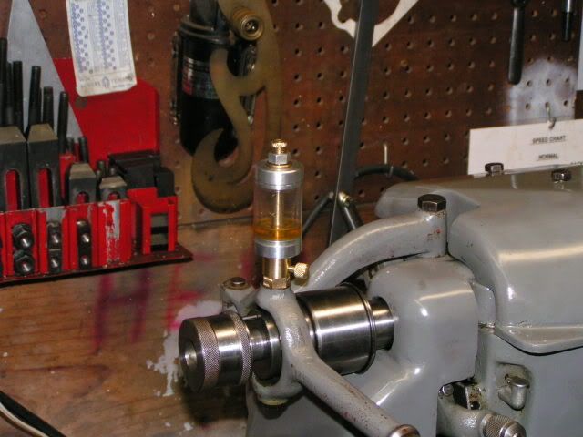
When I got my 10K, it came with a lever style collet closer. Oiling was provided by a simple cup with a flip lid, and the first time I used it, the oil ran out all over the place, and there was no way I could see to control the flow of oil. The lathe came originally with the closer, so I assume, maybe incorrectly, that the oiler was original. Maybe there was a wick missing, or something.
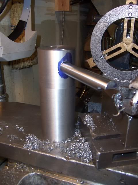
Anyway, I didn't like the idea that there was no way to control the oil flow, and that it seemed to require oil at a rate measured in gallons per minute to keep the oiler full, so I made this oiler to replace it. Now I can control the flow with the knurled knob near the base, see the level of oil remaining, and besides, it looks a lot cooler! :-).
Blob
SteveH8861
Aluminum
- Joined
- Nov 28, 2007
Blob, nice job on the oiler. What did you use for the clear cylinder?
Steve
Steve
Blob
Hot Rolled
- Joined
- Apr 7, 2007
- Location
- Scotts Valley, CA
Blob, nice job on the oiler. What did you use for the clear cylinder?
Steve
Thanks, Steve. You won't believe this - the clear cylinder was cut off of a 3 ft. long plastic tube that came with an American flag I bought last year. The plastic tube fit around the flagpole and was supposed to swivel to keep the flag from winding around the pole in the wind. It didn't work, so I removed it, but saved the tube for I knew not what. I'm glad I saved it; it works a lot better for the oiler than it did for the flag!
Blob
flathead4
Hot Rolled
- Joined
- Sep 28, 2006
- Location
- Spotsylvania, VA
Blob,
Very nice oiler. It's exactly what I need for another little project I have. You wouldn't happen to have a drawing of the internals you could share?
Tom
Very nice oiler. It's exactly what I need for another little project I have. You wouldn't happen to have a drawing of the internals you could share?
Tom
Blob
Hot Rolled
- Joined
- Apr 7, 2007
- Location
- Scotts Valley, CA
Blob,
Very nice oiler. It's exactly what I need for another little project I have. You wouldn't happen to have a drawing of the internals you could share?
Tom
Tom-
Unfortunately I don't have a drawing, as I never made one. On the other hand, the internals are pretty simple. The end caps were turned to the same outside diameter as the plastic tubing, and then a 1/8" deep boss turned on one end of each cap to fit tightly into the inside diameter of the tube. This worked well enough that no sealant was required. The brass piece that mounts the oiler to the closer was drilled and tapped to fit the existing threads on the closer on the bottom, and to fit a 5/16" - 24 threaded feeder tube on the top. In between these two threaded ends is a small, say about 3/32" diameter axial oil passage. The knurled knob that controls the oil flow is threaded into a radial hole that intersects the oil passage just mentioned - it's drilled and threaded 10-32 deep enough so that when the knurled knob is screwed all the way in it completely cuts off the oil passage. The feeder tube is a piece of 5/16" round brass stock threaded 5/16 - 24 on each end, drilled through, and which has 1/8" radial holes drilled in it about 1/2" apart to allow oil to pass from the reservoir into the feeder tube. The whole thing is clamped together with a 5/16 -24 nut and brass washer on the top, and capped off with a knurled stopper which can be easily removed to allow the addition of oil to the reservoir.
I hope this is more enlightening than confusing - thanks for your interest.
Blob
Jerald MI.
Hot Rolled
- Joined
- Oct 21, 2003
- Location
- Clio MI.,USA
Blob- if you forget to shut it off will it seep oil? If so, do all oilers need to be shut off?-Thanks and nice looking piece.-Jerald
Blob
Hot Rolled
- Joined
- Apr 7, 2007
- Location
- Scotts Valley, CA
Blob- if you forget to shut it off will it seep oil? If so, do all oilers need to be shut off?-Thanks and nice looking piece.-Jerald
Jerald-
I dunno about all oilers, but this one will seep if you don't shut it off. :-(
This is a pretty primitive oiler, and I imagine that a better one, maybe with a wick system, might not need to be shut off. There are others on this site that have experience with commercially made oilers - maybe one of them can answer your question.
Thanks for the compliment!
Blob
garyphansen
Titanium
- Joined
- Feb 9, 2004
- Location
- Traverse City, MI
"maybe one of them can answer your question"
They keep feeding oil if you do not shut them off. so if what you are oiling leaks the oil will keep running out. Gary P. Hansen
They keep feeding oil if you do not shut them off. so if what you are oiling leaks the oil will keep running out. Gary P. Hansen
Joe Scope
Plastic
- Joined
- Oct 5, 2007
- Location
- Connecticut
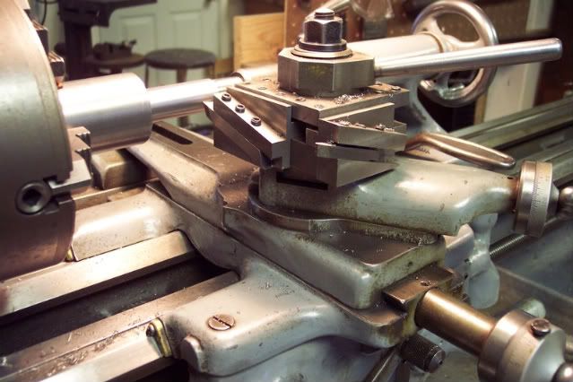
Made this tool holder awhile back. I made two top blocks, one holds 1/8" & 3/16" tool bits the one in the picture holds 1/4" & 5/16". The top block and base is also keyed in both directions so I can index the block 90 degrees on it's base. I designed it this way so I can use the upper blocks on my Pratt & Whitney #3 bench lathe and on my 9" SB with the base to put me on center with the spindle.

Russ Sauer
Plastic
- Joined
- Feb 3, 2005
- Location
- Eastern Iowa U.S.A.
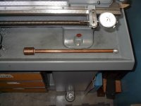
Here's a few things I made for my heavy 10. A spindle nose protector made from aluminum. I copied it from a borrowed original. A knockout bar to remove the headstock dead center. The copper tube is filled with lead shot and the end is solid copper. The knob is aluminum made with my ball turning attachment. A dial indicator holder to clamp on the ways (works on either side of the carriage). The quick clamp is one from a bicycle seat.
Attachments


Blob
Hot Rolled
- Joined
- Apr 7, 2007
- Location
- Scotts Valley, CA
The quick clamp is one from a bicycle seat.
Ingenious use of the seat clamp! Nice!
Blob
bikebuilder
Stainless
- Joined
- Feb 26, 2007
- Location
- Montana
Ingenious use of the seat clamp! Nice!
Blob
As a side note, MSC and the like sell those quick releases as well. Any bike shop should have them in the used bin also.
bb
Jim B.
Hot Rolled
- Joined
- Nov 8, 2004
- Location
- Northern NJ
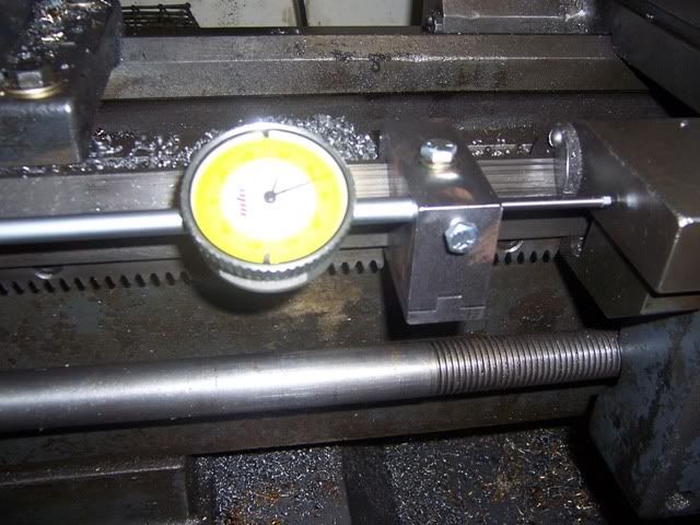
After Seeing the thread on Dial Indicator stops I decided I needed a couple for my lathes, Two for the 9" and two for the Heavy 10. One each for a 1" dial indicator and one each for a 2" dial indicator.
I also wanted the locking screw to be 3/8 square headed so I could use the the same wrench as I use on the saddle locking nut.
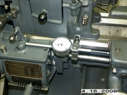
Now I have a 405 with the drum switch in the front and a single tumbler Heavy 10. Both presented design problems. Keeping the dial indicator on the sadle and missing the attaching bracket of the 9" and clearing the gearbox for the Heavy 10. With some work Here is what I came up with for the 9" lathe

And here is the 10L design. The two are different in length and indicator placement.
After completing this project I noted, on this forum, that somone had a dial indicator holder for the QC tool post that you could pop in real quick for setting up a 4 Jaw.
Here is my effort in that area.
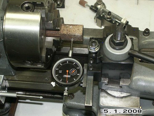
Its a 1/2" square steel bar with 1/4" threaded holes every 0.11/16" There is a Tee shaped bracket that the attaches to the bar with two holes spaced 1 3/8" A 3/4 square by 1" long boss is screwed to the bottom of the Tee to space the indicator away from the QC tool holder.
I used to use a magnetic holder on the saddle. I find this much much easier and better.
The first time I tried it I was within 0.001 on the first try on each axis.
Jim B
I also wanted the locking screw to be 3/8 square headed so I could use the the same wrench as I use on the saddle locking nut.
Now I have a 405 with the drum switch in the front and a single tumbler Heavy 10. Both presented design problems. Keeping the dial indicator on the sadle and missing the attaching bracket of the 9" and clearing the gearbox for the Heavy 10. With some work Here is what I came up with for the 9" lathe
And here is the 10L design. The two are different in length and indicator placement.
After completing this project I noted, on this forum, that somone had a dial indicator holder for the QC tool post that you could pop in real quick for setting up a 4 Jaw.
Here is my effort in that area.
Its a 1/2" square steel bar with 1/4" threaded holes every 0.11/16" There is a Tee shaped bracket that the attaches to the bar with two holes spaced 1 3/8" A 3/4 square by 1" long boss is screwed to the bottom of the Tee to space the indicator away from the QC tool holder.
I used to use a magnetic holder on the saddle. I find this much much easier and better.
The first time I tried it I was within 0.001 on the first try on each axis.
Jim B
garyphansen
Titanium
- Joined
- Feb 9, 2004
- Location
- Traverse City, MI
What have you made for your lathe?
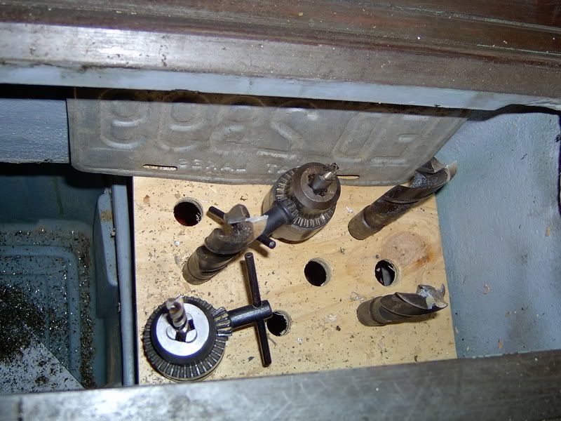
I tried to find the long running thread "What have you made for your lathe" but the "Search" did not find it for me, so I started a new thread. This trick might work for those with a big lathe. It seemed that there was some space going to waste over the right legs of my lathe. So, I just cut a piece of plywood to fit and drilled a few holes. It works good for storage just as long as I remember to take out any tools I might need ahead of time if I am turning something really long so the tail stock covers up my access. Gary P. Hansen
I tried to find the long running thread "What have you made for your lathe" but the "Search" did not find it for me, so I started a new thread. This trick might work for those with a big lathe. It seemed that there was some space going to waste over the right legs of my lathe. So, I just cut a piece of plywood to fit and drilled a few holes. It works good for storage just as long as I remember to take out any tools I might need ahead of time if I am turning something really long so the tail stock covers up my access. Gary P. Hansen
Finegrain
Diamond
- Joined
- Sep 6, 2007
- Location
- Seattle, Washington
OK, so it's not a SB, but there's no Logan forum, so ...
cutting too height gage:
carriage stop/gage:
steady rest:

cutting too height gage:
carriage stop/gage:
steady rest:
Stu Miller
Hot Rolled
- Joined
- Apr 8, 2002
- Location
- Covington, Wa
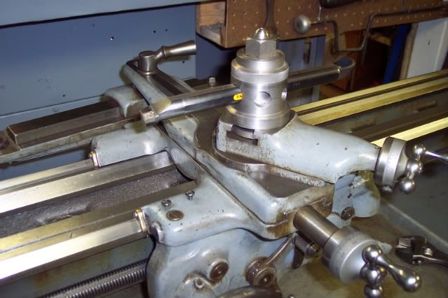
Just to get back on track, here are a couple of projects inspired by old Popular Mechanics articles. I say inspired, because I picked the features I liked best of several versions of each shown in the magazine at different times and combined them into my "own" design.
The first is a 4 position turret type tool post. It is shown with some adapters I made to hold tool bits at about the same angle as obtained with a lantern tool post. It rotates and indexes every 45 degrees.
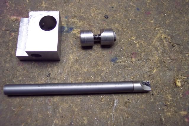
The second is a boring bar holder for a 5/16 carbide boring bar with carbide insert. (a lucky buy at the old Boeing Surplus store for $10.00") )
)
Here is an exploded view. The original was slit and the bar clamped by squeezing the bar with the locking screw. I substituted the locking cotter mechanism advocated in The Machinist's Bedside Companion.
The first is a 4 position turret type tool post. It is shown with some adapters I made to hold tool bits at about the same angle as obtained with a lantern tool post. It rotates and indexes every 45 degrees.
The second is a boring bar holder for a 5/16 carbide boring bar with carbide insert. (a lucky buy at the old Boeing Surplus store for $10.00
)
Here is an exploded view. The original was slit and the bar clamped by squeezing the bar with the locking screw. I substituted the locking cotter mechanism advocated in The Machinist's Bedside Companion.
Stu Miller
Hot Rolled
- Joined
- Apr 8, 2002
- Location
- Covington, Wa
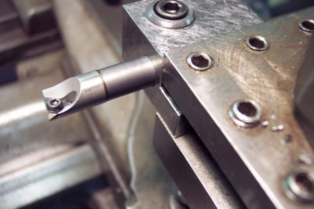
Here is another Popular Mechanics inspired tool, a holder for large boring bars. This one takes 1/2, 5/8. and 3/4 bars directly and others with sleeves. First the holder.
Then the exploded view.
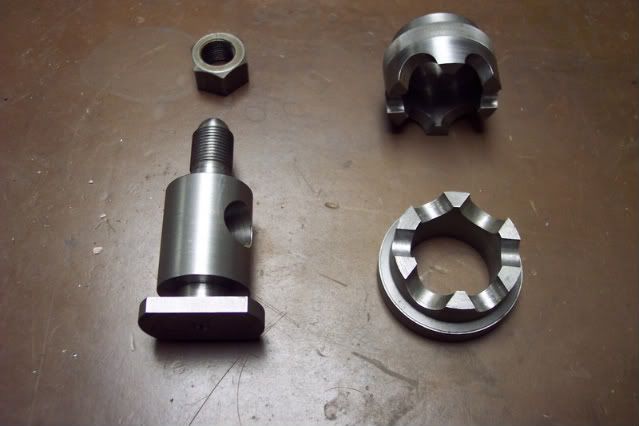
Then the exploded view.
garyphansen
Titanium
- Joined
- Feb 9, 2004
- Location
- Traverse City, MI
Nice looking boring bar holder Stu. I made one based on the same idea but not as nice about 30 years ago. However, now I just use a few Phase II boring bar holders. Gary P. Hansen
Similar threads
- Replies
- 11
- Views
- 500