What's new
What's new

What have you made WITH your South Bend?

Hello. Is anyone interested in making a metric lead screw for a project of mine. I have an SB13 lathe but Im a newby and having belt issue with my lathe. Anyways since this thread is somewhat related to what Im trying to accomplish, i figure ill post it here.
Regards.
Rob a.k.a ub360

You might get more answers if you actually posted dimensions of the part you want.

Belt issues can easily be resolved - post in the main forum for help getting these fixed.
 
20220212_200823.jpg
20220212_200833.jpg
20220212_201047.jpg
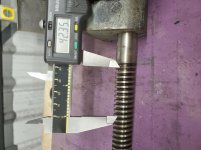
Heres the part. Basically, its an 18mm round , with this thread( odd for 10 threads measured).

I just realized this is actually 6TPI.
the unthreaded part is 84.8mm.
The threaded part is 9.2 inches
Because this is something my lathe quick change gear can handle I might try just it.
 
Last edited:
Heres the part. Basically, its an 18mm round , with this thread( odd for 10 threads measured).

I just realized this is actually 6TPI.
the unthreaded part is 84.8mm.
The threaded part is 9.2 inches
Because this is something my lathe quick change gear can handle I might try just it.

That looks like a square thread. What is this from?
 
Just buy a length of Acme from McMaster?
Thanks for the info. Oddly, this is 18mm and 6tpi. Metrics seem to be listed with spacing between 2 threads with whole numbers in mm. This lead screw measure between 4 and 5 mm spacing, but nicely falls into 6tpi. No 18mm on the TPI section.
 
That looks like a square thread. What is this from?

20220215_091151.jpg
This is the lead screw which I plan to make with my SB13 lathe, since it appears to be acme 6tpi thread. The picture shows lead schrew on top, SB13 cross lead screw bottom. The thread shape looks the same.
 
I started this thread almost 16 years ago. No one has posted a photo of a project they have make on their lathe for almost a year. Lets see photos of some of your projects.
 
16" 1969 vintage. My employer bought it new. I rebuilt it a few years ago (thank you Ted!).

Couldn't find anyone to rebuild the alternator for my 65 Fury Cop Car so I rebuilt my own plus a spare. Made the pulleys. Came out awesome. When I probed the grooves on my CNC everything was within 0.001" worst reading.
 

Attachments

  • Alt Pulley Reduced.jpg
    Alt Pulley Reduced.jpg
    395 KB · Views: 27
  • Pulley Grinding.jpg
    Pulley Grinding.jpg
    199.3 KB · Views: 29
16" 1969 vintage. My employer bought it new. I rebuilt it a few years ago (thank you Ted!).

Couldn't find anyone to rebuild the alternator for my 65 Fury Cop Car so I rebuilt my own plus a spare. Made the pulleys. Came out awesome. When I probed the grooves on my CNC everything was within 0.001" worst reading.
Nice work!
 
  • Like
Reactions: RF
I needed to move some equipment around the homestead that had trailer hitches. My truck could not get to where they needed to go. My dozer could, but it has a large hitch that I made this offset bushing to use a long screw 2" trailer ball.
IMG_20231012_113813372.jpg
Length and diameter are both 1-3/4". Offset hole is 1" diameter. Outside finish isn't the best (1018 steel), but pretty wasn't needed.
IMG_20231012_113821071.jpg
I placed the center of the hole where the bushing would still have 1/8" of material between inside and outside.
IMG_20231012_114038210.jpg
Inserted into the dozer's hitch.
IMG_20231012_115342755.jpg
Ball in place.
 
This is a lapping guide and lap I made to lap the faces of stay bolt sleeves on a steam locomotive.
IMG_0544.jpeg

There are a couple dozen of these that showed a leak between the sleeve face and the cap when a pressure test was performed. Lapping the face improves the chance of a seal between the sleever and the copper gasket inside the cap.

IMG_0503.jpeg
 
was the offset to have full contact of the hitch flange or to lock it onto the large hitch?

The offset was to move the ball away from the latch that is already on the large hitch (it's that thing that the chain is over). With the ball centered, the hitch of the towed implement would contact the latch, damaging the smaller hitch. Offsetting the ball gave enough clearance so that everything tows just fine with no latch contact.
 
Hi Guys,

I saw Gary's thread come back up a while ago, and I thought I'd do a post about the Morrison & Marvin bullet vise I completed a while back. This is an approximately 1/4 scale vise loosely based on the classic Wilton bullet-vise. Morrison & Marvin sold a casting kit to make the vise. The lost-wax castings are very nice quality, and the kit includes a piece of 1/4" acme rod and brass acme nut, various materials & fittings, and a humorous pin, too:

MMVise01.jpg

Here is a shot of the body casting mounted in the 4-jaw for reaming out the bore:

SDC10463.JPG

The nut retainer casting was cast integral with the base casting, so the lathe was used to part off the nut retainer after machining:

SDC10474.JPG

Here's the movable jaw casting mounted in a collet for machining:

SDC10480.JPG

Had to use the mill for some of the operations. Here's a shot of milling out the jaws for the serrated jaw inserts:

SDC10483.JPG

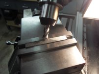
I didn't like the jaw insert blanks supplied with the kit, so I made my own. With the mill vise rotated at 30 degrees, and head rotated to 45 degrees, I used an end mill to cut the serrations:

SDC10453.JPG

Here's the finished vise, perched atop it's "big brother":

SDC13867.JPG

Here's a three-quarter view from the rear. The vise handle and the rotation-locking handles/nuts were custom made from stainless. The inserts are held in the jaws with #1-72 socket-head cap screws:

SDC13871.JPG

According to the Morrison & Marvin website, one of these vises sold on eBay for $1,522.77! That sounds like a lot of money, but I don't think I'd sell mine for that.

While the bullet-vise kit is sold out, Morrison & Marvin also sell a kit for a miniature mill vise, based on the design of the Kurt AngLock vise. I have a set of castings and drawings. Just need to work my down the priority list...

Paula
 
Hi Guys,

I saw Gary's thread come back up a while ago, and I thought I'd do a post about the Morrison & Marvin bullet vise I completed a while back. This is an approximately 1/4 scale vise loosely based on the classic Wilton bullet-vise. Morrison & Marvin sold a casting kit to make the vise. The lost-wax castings are very nice quality, and the kit includes a piece of 1/4" acme rod and brass acme nut, various materials & fittings, and a humorous pin, too:

View attachment 416245

Here is a shot of the body casting mounted in the 4-jaw for reaming out the bore:

View attachment 416246

The nut retainer casting was cast integral with the base casting, so the lathe was used to part off the nut retainer after machining:

View attachment 416247

Here's the movable jaw casting mounted in a collet for machining:

View attachment 416248

Had to use the mill for some of the operations. Here's a shot of milling out the jaws for the serrated jaw inserts:

View attachment 416250

I didn't like the jaw insert blanks supplied with the kit, so I made my own. With the mill vise rotated at 30 degrees, and head rotated to 45 degrees, I used an end mill to cut the serrations:

View attachment 416251

Here's the finished vise, perched atop it's "big brother":

View attachment 416252

Here's a three-quarter view from the rear. The vise handle and the rotation-locking handles/nuts were custom made from stainless. The inserts are held in the jaws with #1-72 socket-head cap screws:

View attachment 416254

According to the Morrison & Marvin website, one of these vises sold on eBay for $1,522.77! That sounds like a lot of money, but I don't think I'd sell mine for that.

While the bullet-vise kit is sold out, Morrison & Marvin also sell a kit for a miniature mill vise, based on the design of the Kurt AngLock vise. I have a set of castings and drawings. Just need to work my down the priority list...

Paula
Nice job. Glad to see you posting again.
 
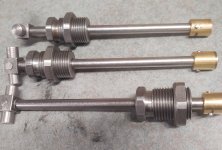
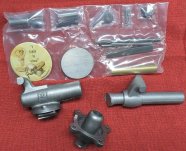
The worn out '28 9C 4' and I are making some water pump packing nuts that fit most models of my brand of Twin City/VERY early MM tractor engines (1925-1939). More governor parts above are out of focus like Jan 20, 23 for another model tractor^^.
Other than the "my fault" chatter marks in no. 1 on the left's bore (for a counter clockwise engine), there's a couple subtle differences between the RH thread prototype and the LH thread "production" (clockwise engines) packing nuts.
Sure like that quiet old lathe. Make parts and hear the radio.
 

Attachments

  • 1. Trials-x.jpg
    1. Trials-x.jpg
    518.2 KB · Views: 5


Back
Top