What's new
What's new

Whitcomb planer

20220521_152621.jpg
20220521_152635.jpg
20220521_152630.jpg
20220521_152642.jpg
20220521_152656.jpg
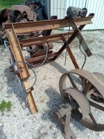
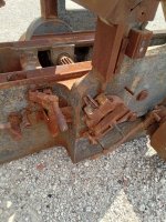
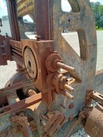
Here's the overhead stuff. The framework is of course aftermarket, but as it's held together all with square head bolts, I think it's "old" at any rate. The part of the rack that's white or grey only holds the jack-shaft assembly and the bearings for it appear to be meant to be mounted with the hangers under the shaft (like it sits in the photos). There are also some un-used large square head bolts in the back of the columns that seem to imply that this machine may have come from the factory with the overhead jack-shaft mounted on the machine, not a ceiling mount configuration, and at some point they may have broken the original cast iron brackets, or needed to change where the jack-shaft sat above. I'm not sure if that implies it was an electric machine from the beginning, or perhaps they used to offer shaft driven machines that just had the jack-shaft mounted to the machine (semi-mobile version of the machine). The parts of the frame that hold the motors were all added at a later date, as they were stick-welded together and not painted with the main framing. The little gear head motor was added for operating the power feed and has a little variable-speed controller with it, but I think it'll be one of the first things to go in favor of putting it back to belt drive, as all of the pullies seem to be there to do so. The Jack-shaft has also had some bits sawn off the castings and shaft to operate a now gone clutch. The shaft is bent and will need to be taken apart to straighten or replace anyway, so when that happens I'll look into recreating the clutch function.
 
20220521_152712.jpg
20220521_152705.jpg
The main motor is a 7.5 HP beast. I think this is the first time I've seen "squirrel cage" used an an official motor description on a motor. I'll be looking for a new home for this motor if anyone knows one.
20220521_152835.jpg
And last picture is the "loose" parts that were saved on this first trip. The head that's still on the machine still has a tool holder in it, but I'll be on the look-out for more as all of my lantern-style holders are a bit small for this application.

One other thought with the measurements above is that they confirm a suspicion I had that the "earlier" machines had shorter beds than those advertised by the 1920's. I think it's safe to assume that this machine is lighter than the 12,000lbs. advertised as it's at least 24" shorter, and I'm sure the iron's a little thinner as well. Fully assembled, I'd estimate the machine to be no more than 10,000lbs.
 
Last edited:
View attachment 365243
View attachment 365244
The main motor is a 7.5 HP beast. I think this is the first time I've seen "squirrel cage" used an an official motor description on a motor. I'll be looking for a new home for this motor if anyone knows one.
View attachment 365245
And last picture is the "loose" parts that were saved on this first trip. The head that's still on the machine still has a tool holder in it, but I'll be on the look-out for more as all of my lantern-style holders are a bit small for this application.

One other thought with the measurements above is that they confirm a suspicion I had that the "earlier" machines had shorter beds than those advertised by the 1920's. I think it's safe to assume that this machine is lighter than the 12,000lbs. advertised as it's at least 24" shorter, and I'm sure the iron's a little thinner as well. Fully assembled, I'd estimate the machine to be no more than 10,000lbs.
You don’t see planer tables with the drilled holes for stop bars over here.

Regards Tyrone.
 
You don’t see planer tables with the drilled holes for stop bars over here.

Regards Tyrone.
With a couple exceptions, they're drilled all the way through too, so chips and other debris will drop through.

The bed has open box sections from end to end, with the only bottom access being at the far ends, so another task I'll have is fabricating some sheet-metal covers to keep chips from falling in, then it's just a matter of sweeping off the covers when they're exposed.
 
Something I could use some help with is with the 2nd belt drive assembly, what diameter is the driving pulley suposed to be? Since the old metal one was replaced with the now decomposed paper one, I want to be sure I replace it with the right size. I think it's also missing the idle tensioner pulley and they were just running it with a tight fitting belt, so I'll have that to make too.

Also, am I correct to think that all of the operators controls are on the right side of the machine? I'm thinking that the plainer will sit in a corner with a couple of feet between the machine and the wall on the right side (just enough room for maintenance). I'm thinking the only time I'll need access to the left side is if I'm setting up to plain the left side of a piece. It looks like the cross rail extends a little further on that side too.
 
Last edited:
Yep, every planer I’ve ever worked on had the operator’s station on the RH side. You need to leave some space for the withdrawal of the cross rail leadscrew and feed shafts on that side. Either that or put a small hole in the wall in the right place.

I’ve never worked on planer tables so small to be honest but on the bigger ones over here there were dome shaped holes cast into the table running from one side to the other side. On some machines there were also holes running down from the tee slots into these holes to let the chips down and out. On other machines the side holes were covered over with sheet metal plates.

The holes in the side of the table were also for rigging the tables. You put lengths of 3” steel bars into the holes and hammered wedges into place to fasten the bars in position. Then you could lift the table. Obviously you couldn’t use eye bolts to lift tables weighing 20,000 lbs or 30,000lbs.

Good Luck with the job, Tyrone.
 
Last edited:
Nice progress!
I haven't checked in in a while.
Will try to get 2nd belt drive parts sizes later today.

Mine has a lever on the left side, you can see in previous pics where i adapted it to take cams for the airlifter. This lever is not quite as easy to use (over sensitive to hit the neutral position) as the control on the RH side, but if you practice, it works. Both sides are interconnected. Of course mine is a few years later than yours, so don't know if it was included during that previous era.

smt
Thanks!

It looks like the cross rail screws have sockets on the left too. I'm guessing the left side control is just for jogging things during set-up and as a safety? I'll plan on leaving enough room for someone to be on that side just in case. Even without controls, if the machine were to slip into motion while setting up a job from the left side, I'd want to be able to stand back. Once it's on a pad and powered up, I'm thinking about making some simple wood stanchion's for the front side of the machine that'll likely block off the left side as well. Even if I'm smart enough to stay out of the pinch zones, I'm sure I'll have visitors that want to see things working, so having established safe-zones will be prudent.
 
Last edited:
For the "Second belt drive" on mine:

All 3 wheels are aluminum (for low inertia)

Driver- 12" dia, 3" wide, slight crown, grooved circumference. Looks like 6o deg thread tool, but it is not a thread (not helical). 14 gpi (Might be 13 gpi, hard to get my head down there and i don't see fine stuff as well anymore). The crests are flatted - sharper toward edges of the wheel, meaning the crown wore more.

Driven/Bullwheel - 20-1/8" over the crown x 3" wide. Smooth face. Crown is 'more than 1/16", certainly not 1/8".'

Idler - 6" dia. x 3-1/2" wide, flat face. (no crown)

The cross rail screw & feed rod can be cranked manually from either side so long as the pawl is in neutral on the leadscrew, on the RH side. You are correct that under auto feed, it is necessary to be on the right to flip the pawl on the rail feed. It is driven by a rack beside the column, up from the table forward/reverse linkage; and there is no rack on the LH side of the machine The toolhead has it's own tiny lever for downfeed when the feedrod is selected by transfering the gear & pawl set to it (still on the RH side of machine). Funny how quickly my memory of the controls evaporates without standing in front with recent use. Can't picture some of the details on the toolhead itself at the moment.

As mentioned, the table can be operated from either side on mine, but sloppy linkage from the left side makes it a nuisance to hit neutral reliably. It is easy to flip from forward to reverse & back again; so long as the table is fairly under way to let the belts shift easily.

I'm curious how wide the forward belt from the overhead is, on yours. Mine is 1-3/4", and it will slip in a heavy cut. My motor is only 3HP gearmotor which has mostly seemed adequate since it will chug along even when the belts groan and slip. Supposed to take up to 5HP and the machine is heavy enough otherwise.

As mentioned, a VFD is a seriously appreciated accessory on mine. I sometimes use carbide tools, and sometimes plane aluminum. Then there are the times there is a router in the tool slide, cutting wood, so need to creep feed it at 15Hz with the overhead flatbelt cones in the lowest position.

Nice to see the progress you are making!

smt
Thanks! Those dimensions will be a big help. I have some sheet-metal and iron 12" pulleys, one of which should do for a replacement until I can find or make something in aluminum.

My machine doesn't have any belts, other than an old webbing/composite belt on the 2nd-belt drive, but I'm guessing 2" would work for the down belts. I'll have to measure the main drive pulley on the right side and see how wide I can get away with before It starts having issues shifting. On mine, they (factory or past owner?) drilled a bunch of 1/4" holes around the perimeter of the drive pulley, I assume to give a little more traction. The upper pullies and the lower idle pullies are all solid iron.

Since I'll be powering this project with a gas engine, my plan is to set the throttle lower or higher when I need a speed that the cone pully machines don't have. As long as my main shaft can take the speed and I drop belts from machines and jack-shafts that I don't want running at a higher speed, I should be good. The plainer just has a single pulley for input, so I'll need to match it with a pully on the main shaft that gives a good general speed. The main shaft will likely be running somewhere between 250 and 400 RPM most of the time, and will be running in Babbitt bearings with ring oilers.
 
Yeah, when the planer is running, the overheads don't stop or reverse, so heavy iron flywheel effect is good. Driven pullies are CI on mine, but the idler in the center is aluminum. Might help a little bit with faster shifting, since every belt swap reverses it. OTOH the outer pullies, being keyed to the same drive shaft, are reversing, too....

The motor on mine is from a 19-teens 3ph 3HP floor polisher - i suspect a terazzo tile grinder, but never found much on google back then. It is 800 rpm at the motor, and 100 rpm out of the actual output shaft after planetary reduction. It then has a set of 3 step, 4" widebelt cones. Will have to check the top/bottom ratio next time out there.

But i think your overhead lineshaft rpm's will be fine.

smt
 
Well it's happened. I've got the plainer sitting behind the shop!:D Unfortunately didn't get to get any pictures yet, but they're coming.
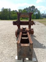
Dave was super helpful using his trailer to get it to my side of the map, and our little forklift proved not to be so gutless as I thought. We were able to lift one end and roll some pipes under it, pull it over the end of the trailer and set it down on some blocks, then lift the far end to drive the trailer out from under it. Nothing broken.

One observation. It looks like all the pullies are steel or iron. So this either predates the aluminum pulley feature, or they were replaced.

I don't want to get too into rebuilding this thing yet, but as the missing gear rack will be a critical step, I'm going to start by getting the ways cleaned up and setting the table back on so I can get measurements to machine the replacement rack.
 
Nor is, particularly tearing down and erecting most machines. OTOH i will not bore you, nor re-pain myself with an account of some quite wonderful machines that were perfectly capable - until i took them apart to get them home, and stored them. Some inside, some outside, under plastic with tarps on top.... for the first few years.... Not that i am cured. 2 neighbors still have sections of their barns (down from 3, one guy passed on) with my machines and such in them.

OTOH when i have made a priority of getting a machine into the shop, into service and functioning, it seems i find a way to keep using it and improving it, and finding ever more interesting and productive ways to keep using & improving it.

The issue is that there are so many interesting things to do in life, that it is way too easy to find a decade passed before you get back to a project left half-undone, if you don't do it now. Almost every week brings another opportunity or distraction in some direction. You may come back around to an old project, or it might be in your estate sale. If it's important to me, i try not to let there be a lapse in the proceedings anymore. As far as work on my planer, it runs and runs well enough to do quite good work for most of my purposes. It was not bought as a toy, i realized after scraping several large-ish machine tables and elements too large for the mill or 30" surface grinder here, that it was stupid to keep doing that without a planer. My point about fantasies is to not let ideas of perfection prevent you from using what you can and making it a productive asset that does not cost time to use. The reason my planer improvement fantasies are that, is that as i look around and wonder how long i'll be in fortunate good health, activities i neglected or put off for years, decades even, seem far more important for time allocation these days while health does permit. Skiing as much as possible in the winter, flying as much as affordable in the summer, working on my own house & projects for a change.... Life's a continuum on the matrix of time, money, and health. Allocate fortuitously.

smt

I'm actually going to print this out and tack it to the wall near my desk in the office. This is good insite for those that are too busy acquiring projects to realize what stage they are at. Not that I'd ever do such a thing....
 
20220704_160952.jpg
20220704_161002.jpg
20220704_161010.jpg
Inventory tag on the front of the bed.
20220704_161030.jpg
So this 2nd belt drive isn't like the others. As noted before it doesn't have any aluminum pullies. I had thought that it was missing a belt tensioner and the belt guides were welded afterthoughts, but they are original cast iron, and the whole back shaft adjusts fore and aft to set the belt tension. Guess it's an early design, but other than the decomposed paper pulley, at least there are less parts to replace.
20220704_161054.jpg
Looks like the main drive pulleys and related parts are all in good shape. The shippers have been broken and welded a few times however. Note the middle pulley full of holes for traction. It also looks like it's had a section riveted to the inside to tie a crack together.
 
20220704_161058.jpg
20220704_161111.jpg
20220704_161115.jpg
20220704_161123.jpg
20220704_161127.jpg
Note that most all of the parts that appear to be missing are accounted for. They were just removed to lighten the load before this thing went to the scrap yard, but I got them on the first load with the table. Might be some missing fasteners or such, but otherwise, the table gear rack is the only missing piece. Replacing that and de-rusting everything will be the biggest tasks to getting this thing operational.
 
20220704_161131.jpg
20220704_161135.jpg
These table way oiling rollers are heavily pitted and likely will need to be replaced. Not sure if there's some kind of oil drain in those pots that is plugged up.
20220704_161148.jpg
The oil reservoirs for the table pinion look like they have stayed sealed. Most of the machine is pretty stiff from rust, so will need to start soaking it all in oil.
20220704_161217.jpg
These are the back four bolts that currently do nothing, but looking at catalog images and shadows in the paint, I think these used to hold the upper jack shaft, and it wasn't on the ceiling when it was new.
20220704_161231.jpg
Another inventory number, "591".
 
20220704_161303.jpg
The patented cross bar binding mechanism.
20220704_161315.jpg
20220704_161409.jpg
Even though they were using the variable speed gear motor for power head adjustment, the original belt drive parts including it's forward/reverse friction clutch arrangement and lever are all still there.
20220704_161425.jpg
Here you can see the sliding bearing for the 2nd belt drive tension adjustment. There's even a wood plug covering the bearings oil hole. Not a lot of visible wear so far, just occasional old damage repairs.
20220704_161513.jpg
There are a pair of hanging weights balancing the shifting mechanism, still hanging from some galvanized cables.
 
Way to go!
Except for the 2nd belt tension method, your planer is very close to mine and it has most of the good details, including the sliding wedge/cam-lock rail.

You show some details i don't know if mine has, like the weights on the shifter rods. IOW, i can't see them externally as you show, and never investigated closely inside.

I never found any drain holes in the oil wells, seems that would be unusual.
You can see at the ends of the Vee's though, that there is a weep hole in each, for the oil to gradually drain out onto your floor as the machine works. :)

Maybe i missed it -
So, how wide between the columns?
How long is the bed?
And the table?

You've got most all you need to work with.
Except maybe the rack for the rail increment?
You've got 2 heads on the rail, so the shifting part of the leadscrew and feed rod engagement is considerably different from my single head machine.
With the oil wells, If nothing turns up under the debris, I think I'll drill and tap a couple holes in the side for 1/8" or 1/4" NPT plugs. Short term that'll keep moisture out and long term it'll help cleaning and flushing the ways.

The table ends have the holes that go onto the ground, but there's something with the casting between them, and Dave thinks he remembers some kind of catch bucket hanging inside on each end of the machine that disappeared while he was getting the machine from the prior owner. Might not be a bad idea to run a little copper tubing and hang a couple little cans under there to catch drips.

This Plainer is the 30"x30" with a 10' table. The bed casting measures 21" wide by 12', 7" long, while the overall width of the machine is approx. 6'. The table is 26" x 10' overall, with 97 1/2" of working area in the middle (not counting the trays on the ends).

I think I have the rack you're talking about. Now that the machine is here though I'll lay it all out and double check.


Back
Top