What's new
What's new

winter project: P&W toolmakers compound

Was away visiting the offspring unit, so now more photos of recent progress, on the "A" surface of the slide. Took a fair bit of work and it's not really done yet. I'll never be able to remove the really bad dings near the far end but most everything else is about there. The thing I haven't yet checked is the parallelism between the top and bottom which may cause me to regret doing this from the git-go. Two photos, same surface, different lighting. The red outlines are still keep-away zones.
 

Attachments

  • pw_A1.jpg
    pw_A1.jpg
    102.3 KB · Views: 92
  • pw_A2.jpg
    pw_A2.jpg
    97.6 KB · Views: 89
New top slide has been fabricated and scraped in. Also re-machined the dovetail ways on the lower part of the assembly. Some lessons learned the hard way:

1) if you clamp something down to the mill table be sure you are clamping on the correct surface. The swivel way on the bottom of the lower slide stands proud of the ends of the slide, so when the part is clamped at the ends of the slides, the part *bows*. Once the dovetail 45s are cut and the part is unclamped, the slide ways now have four thou of bow, tall at the ends and low in the middle. Much fun to set it back up so the ends were at equal height so minimal material had to be removed.

2) simply milling a surface no matter how carefully means it takes *forever* to clean up when scraping. After that realization, all surfaces were fly cut.

3) the slide way worked fine but the gib screws were way out there, because of the material removed, and because I mistakenly copied the exact dovetail dimensions when I reproduced the top block. I fabricated a new gib, and figured out how to scrape that in (took a while to do that, it was a pocked in a nylon block that just fit the gib dimensions, and left the surface 50 thou or so proud.

The nut had to be trimmed a bit to fit because of the lowered height of the assembly, to clear the bottom of the gib.

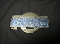
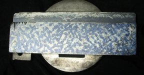
Right now the bearing surfaces are on the "B" surface as shown in the former photos, and of course the 45 degree dovetail surfaces on both sides. The A surface is close to bearing, with a bit more work I could get full contact on both the A and B surfaces. The former scraping job had to be trashed as when it was all done, the top surface ran out about 0.008 from parallelism with the dovetail ways. Fly cutter to the rescue again. In that photo I really had not properly scraped in the flat ways visible on that part yet. I had to make a special tool to get into the corners.

I did scrape in the top of the T-slot because it's a very visible piece, and it was easy to do.
 

Attachments

  • block_1.jpg
    block_1.jpg
    94.7 KB · Views: 54
  • gib_1.jpg
    gib_1.jpg
    77.4 KB · Views: 49
  • block_top_1.jpg
    block_top_1.jpg
    96.9 KB · Views: 50
  • top_way_1.JPG
    top_way_1.JPG
    80.3 KB · Views: 54
Seen now in a more assembled format, not done quite yet, a few more things to do.
 

Attachments

  • slide_complete_3.jpg
    slide_complete_3.jpg
    66.6 KB · Views: 55
  • slide_complete_1.jpg
    slide_complete_1.jpg
    50.8 KB · Views: 50
Nice! It looks great :)

I had to make a tiny little tool to get inside those dovetails. I've used it quite a bit since as most of the stuff I am scraping is similar in size.

I had to modify my nut too, I moved it a bit in and had to remove some thickness from the flat section. Once I had it close I re-drilled the dowel pins that lock it in place a bit larger using the old holes to guide it. That has worked well, I've been using it for a few years at this point.

I love the tapped holes on the end- I made an eccentric shaft that engages/disengages 2 gears so I can use it for threading up to a shoulder (its my only lathe so I make do...). I know I saw a picture of what P&W meant to go there but I can't remember what it looked like, and didn't save the photo like I should have.

Here's a few shots of mine
P&W slide 4.jpgphoto 2 (3).JPGphoto 3 (2).JPGscrewcutting1.jpg
 
Great frosting!

I had to make a teeny transfer punch from a 1/8 dowel pin to get the holes from the nut into the new block. Also a bit of a trick to get the oil holes for the nut oiler lined up.

The pins for the nut seem to have a very slight taper on them - plus the assembly seems to be a ship-in-a-bottle thing - the pins have to go in last, as the block can't slide over the nut with them in place! My next goal is to put the oil channels in the gib and underside of the slider block.
 
Help!

I'm re-doing the lower, cross-slide ways. The gib was missing, so I used the technique formerly used to make the shorter gib for the tool block, which turned out nicely.

I roughed out the part on 9" long chunk-O-cast iron, profiled the angles, and cut it off. Once cut off it developed a roughtly 3/16 bow in the center. The
cross-section is spot on, over the entire 9" length. It's 1/8 thick, by 9", 45s on each corner.

Can this be heat-treated to relax the internal stress, to make it lay flat? Is this a common feature of making long thin parts like this from cast iron?
 
Heat treat might help, but you will probably have to restrain it in the straight position, or at least put a dead weight on the bow to encourage it back toward straight.

Richard King mechanically straightens gibs that have bent in the process of reconditioning. Convex bow up, support the ends on small spacers, use a C-clamp or similar manual screw to cautiously bend the bow back toward neutral. Obviously, cast iron isn't very ductile, but it is ductile enough for this to work in many cases. What I don't know is if the stresses you relaxed in manufacture are much greater than the stresses relaxed during reconditioning. If so, it may not be ductile enough.
 
Thanks. I'm a bit hesitant to do an "instron test" on this part yet. But then again, I made it once and I've a lot of stock for another one if a break this.

The bow is so slight the parts mate together fine. I'd just have a tough time scraping this one flat right now. I have no idea how hot they'd have to be
to stress relieve, but I suppose a session in the oven at 500 F might be worth a try.
 
IIRC, normalizing and stress relief anneals are a lot higher than that 500. And on CI I don't know how well it works.

Might you hold the part straight and heat it up to stress relief temps? Does that work on CI?
 
That’s a lot of bow!

It would have been best to stress relive before machining.

I would try to bend it back cold.

This was machined out of a 9" X 1" X4" chunk of gray cast iron - if I can't figure out how to stress relieve a small part like the gib, doubt I could do the stock it was cut from.

The maching steps were: deck the top to flatten the rough top, cut the back side to flatten that, then machine the front side to set the overall width of the part.

Next I used a 45 deg dovetail cutter to form the one angled side, and a 45 chamfer tool (well, 90 deg included angle plain cutter on an arbor) to form the opposed 45 deg side.

Last was to cut the part out to the correct 1/8 thickness, using a woodruff key cutter as cut-off.

All this was done via the vertical spindle in an FP2. All operations wer carried out with the piece in place in the vise. The part looked OK during the entire process but clearly something during some step intoduced some stress.
 
Thanks for all who commented - I put a body-work dolly in the vise this morning, with the longest radius curve facing up. The part could be gently bent over that curve to good effect, it's now flat enough to start spotting and scraping.
 
Just a comment on informal stress relieve. I had a small dovetail straightedge I wanted to normalize before finish scraping so used the wood stove to bring it to red heat in the coals and then let it cool off overnight. That isn't a verified temperature, but it should be somewhere in the range. And it has stayed straight since, though that alone doesn't prove anything. It might have been okay anyway. It might still be early enough in the season that a wood stove isn't done for the year.
 
Did not have to resort to heating, it came straight enough for scraping by bending cold.

My main problem now is, I need to replicate the nut for the cross slide bottom. The lead screw that P&W put on there is 0.340-20 thread!

a) single point out of bronze, or
b) make a tap.

The saga continues.
 
And the answer is: single point out of bronze. Specifically, out of a used, bronze valve guide that had the correct ID, length, and OD, just about.
 
You single-point threaded a .340 diameter internal thread? My hat's off to you. How long was the bore, and what did you use for the tool?
 
Thanks, not that tough - the nut only wound up being 3/4 inch long, and the part was open at the back end so no need to stop at any particular place. This was a small pre-made threading tool wit a round shank (bokum type?) and the job was likewise easy because I could offer the screw up to the part, in place to test for fit.
 
What the final assembly looks like. The nut was installed with green locktite. One trick was, the lower cross-slide was not original to this assembly, so the bore for the screw was far off from being in the correct location. My solution was to re-make the end plate, with the bore for the screw assemebly in the "correct" location.
 

Attachments

  • final_assembly_1.jpg
    final_assembly_1.jpg
    65.4 KB · Views: 36
  • final_assembly_2.jpg
    final_assembly_2.jpg
    76.9 KB · Views: 35
  • final_assembly_3.jpg
    final_assembly_3.jpg
    78.8 KB · Views: 39
Nobody caught the boo-boo there. The two micrometer collars were swapped on that, the crossfeed screw is 0-100 divisions and is direct reading for diameter, the longitudinal feed screw likewise direct reading in distance, and goes 0-50. Somehow (former owner, me during the clean-up?) they were put on backwards. Fortunately it's easy to just swap the collars on the bushings.


Back
Top