What's new
What's new

winter project: P&W toolmakers compound

jim rozen

Diamond
Joined
Feb 26, 2004
Location
peekskill, NY
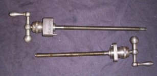
I'm partway through working on a fairly trashed out pratt and whitney toolmakers compound, and have a few questions about the cross-slide - basically questions that have been on my mind for a while about dovetail slides like this.

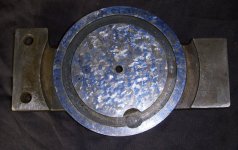
What are the actual bearing surfaces on a slide like this? There's a block with a female dovetail that slides along the length of the cross slide. Front side has a gib with three adjusting screws, the back of the block bears on the back of the male dovetail length.

It's apparent that there should be contact between the angled dovetail surfaces, and tighting the adjusting screws obviously makes the underside of the rear flat surface bear on the top of the flat surface of the back of the cross slide.

The underside of the *front* of the block has a bronze nut screwed and pinned in place, and it's obvious the flat underside of the bronze nut body does *not* bear on the front flat part of the slide, there's lots of clearance there and no wear marks on the bronze.

So the question remains, what kind of bearing is supposed to happen between the top flat surface of the cross slide, and the flat underside of the traveling block?

Is that designed for clearance, or for bearing? If bearing then it's apparent I'd have to a lot of work as the topside is pretty chewed up near the left end. And the bearing would be a bit over-defined as it would have to be simultaniously the rear flat, the top flat, and the rear dovetail.

How are these typically done at manufacture?

Really this is just an projet to practice on, as I'm missing the lower part of the cross slide. But it's a nice assembly, one of the modern P&W ones with ball bearings on the screws. Any comments gratefully appreciated.
 
I'm a bit confused by your use of "front" "Front side has a gib" suggests the side facing the headstock. A leadscrew nut would normally be mounted along the centerline between the two dovetails, but you write it's "underside of the *front* of the block". Can you provide a sketch or a photo showing the underside of the slide/block?

I am not familiar with this particular machine, but usually the large flats between the dovetails do not make contact, and the narrow flats exterior to the dovetails make face-to-face sliding contact. As you noted, the gib applies an force to the dovetails, and the angle of the dovetails (both sides) forces the narrow flats into contact.

I'll have to take some photots, yes - It's a toomaker's compound and the slide in question is parallel to the bed, so front means towards the operator, rear being away from them. The three gib adjust screws are visible from the front.

Ah, here's an example, this was a BC Ames slide. It has only two gib slides but the idea's the same. In this case, years ago, I decideded there was no contact on the top surfaces. Not sure about the one I'm doing now though.

pw_lathe_B4.jpg


The bronze nut on that works the same way - flat portion pinned and screwed to the front, underside of the tool block.
 
Fairly common. Rivett the same, as are many watchmaker's lathes.

The nut is on an arm that is secured to the slide, and extends through a slot to reach the feedscrew. You can see what looks like the slot at the bottom of the dovetail in the picture above.

If you are going to do milling etc on the machine, and especially grinding, the closed top of the slide protects the screw. That may be the primary reason for what is otherwise a somewhat silly arrangement.

In most cases no contact between the top of the dovetail and the sliding table. Just along the underside of the dovetail, and the adjacent flat.
 
Photos as promised. So the specific question is, are surfaces A, and A' supposed to have bearing?Obviously B, and B' do. The bottom of the nut is C' and that does NOT bear on C. Of course the dovetail surfaces all do. (the N shows where the bronze nut mounts, no bearing there) As you can tell the tool block itself is very, very rough. This is a candidate for replacement from bar stock.

Other photos show the details of the nut mounting and the screws which are fairly unworn and in good shape.
 

Attachments

  • PW_2.jpg
    PW_2.jpg
    84.7 KB · Views: 136
  • PW_5.jpg
    PW_5.jpg
    97.7 KB · Views: 110
  • PW_6.jpg
    PW_6.jpg
    97.7 KB · Views: 106
  • PW_7.jpg
    PW_7.jpg
    75.6 KB · Views: 108
  • PW_8.jpg
    PW_8.jpg
    49.5 KB · Views: 98
For those interested, progress on the parts I've worked on so far. And what I believe may the answer, the one I was hoping not to hear, is a photo of a New Old Stock hardinge model P slide. I cannot slide a 0.001 piece of shim under the block, and when I marked the top with a sharpie, the dried ink smeared when I ran the block over it.
 

Attachments

  • PW_3.JPG
    PW_3.JPG
    96.8 KB · Views: 131
  • PW_4.JPG
    PW_4.JPG
    86.5 KB · Views: 128
  • Hardinge_P_2.JPG
    Hardinge_P_2.JPG
    85.5 KB · Views: 133
I’ve rescraped a few of these slides, and this particular P&W one specifically. I figure the A-A contact is crucial, being the largest surface. I’ve been prioritizing it above the B-B surface, although they should both be fit.

I have a few of these in pieces if you are looking for the bottom half.
 
Thank you yes, that's the one part I'm missing. And I figured the flat contact between the parts would be the most imporant, given that it will be the hardest for me to achieve given the worn condition of the tool block. Probably I'll need to make a brand new one given the wear.

The BC ames slide I "sort of" re-did years ago, never did have that flat contact bearing, but it works well enough. The milling marks on the topside are quite apparent.
 

Attachments

  • BC_ames_2.jpg
    BC_ames_2.jpg
    72.2 KB · Views: 100
Well you have the "alternate" system.

Yours rides on the dovetail itself. I do NOT think the "B" surfaces have any role at all then. Obviously the gibbed portions provide the opposing surface.

The other system uses NO part of the "A" surface (in general) but uses the gibbed surfaces against the "B" surfaces. For that, the nut is inset so as not to cause an issue. You can see an inset nut here: Rivett 608 Photo Essay Page 2

The top and gib such as you have, is not too difficult to scrape.
 
I'd be surprised if the Rivett compounds as shown in those pictures didn't have full contact over both A and B surfaces. Its not that hard to get them all matched reasonably well.

For doing A, I scraped the large A surface flat and parallel to the underside and then used it to spot the underside of the topslide. The B surface didn't interfere initially when I was doing it but if it did you might still be able to do it this way by just flipping it around. The topslide scraped very differently than the rest of the parts, like it was a different material. I wondered if it was steel? I was able to get it fit, but it didn't look as nice as the other parts. If I was doing it again, I'd scrape both A and B parallel on the longer part, measure the difference between them, and then put the topslide in a mill and carefully fly cut the A and B surfaces the correct distance apart. That would simplify the scraping.
 
That rivett probably had contact on the A, B, and C surfaces. Unlike my P&W slide, the nut on that is inlet into the front surface of the tool block, so it can have full contact on that surface. My main worry about getting full contact on the top flat of my slide is that it will mean moving the toolblock *down* to regain that contact (see the wear on the underside of the block, visible where the surface transitions to the area where the gib bears on it) which means the block will move *forward* quite a lot and that will shift the screw axis forward. From past experience the shift on that axis will put the nut and the screw centerline about 1/8 off front-to-back and about 1/16 inch up-and-down. This slide in particular will be problematic that way as the far end of the screw is held in a real ball bearing at the left end of the slide.

I think my best bet is to get the geometry on the slide correct (top flat, parallel to the bottom, side ways flat and equal height, and the dovetails straight and aligned with each other) and then fabricate a new tool block to fit that.

The BC Ames slide I showed seems to work pretty well with the top surface not in contact (I used that a lot before a bought a schaublin side on one lathe) and it always seemed to work OK. But given this is a project to improve my scraping skills, I'll probably do it the long way.

Also: note that the Ames tool block has the same "inlet" setup for the nut as that rivett one. It has full contact on the B and C sides, as well as the dovetails. Interestingly the altitude of the B and C surfaces differes by about 0.1 inch on that slide.
 
I'd be surprised if the Rivett compounds as shown in those pictures didn't have full contact over both A and B surfaces. Its not that hard to get them all matched reasonably well.
.................

Mine, which has a t-slot top, and not the eccentric toolholder, does NOT have that full contact. The top surface, the "A" surface, has not contact, although it is a close fit. Even after re-scraping the fit of the "B" and underside of dovetail (D), there was no contact on the top. And no wear marks there either.

It is not necessary mechanically (although when did that ever stop Rivett?), and that surface is very open to piles of swarf.

If you look closely at the pics in the link, there are wear marks on the "B" surfaces, but none at all on the A. That corresponds with mine, and that pictured unit has an obviously original eccentric toolholder.

The inset nut arm indicates that there was definitely contact intended with the "B" surfaces. There is no "C" surface at all, and even on the PW, it seems unlikely that contact there was intended.

The provision of what look like oil grooves on the PW for the "B" surface seems suspect. If the "A" surface was the intended contact (and it must be, as "C" is discontinuous and just not a good candidate), that is sufficient for stability.

As for the movement, it would seem that A', and the inside of the dovetail opposite the gib, could use to be built up with turcite or other appropriate material. That could restore the original relation of parts.
 
The B surfaces on mine do show heavy wear - it's apparent that's a bearing surface. The oil grooves are fed via a blind plugged hole that goes front-to-back. I eztracted the two oiler ports on the top - one does the slide ways, and the other feeds the *inside* of the nut via another blind, plugged off hole that goes the WIDTH of the nut body and connects up to the vertical passage to the oiler port. All of which was packed solid with glop....

I think I'd want to avoid polymers for this project, no matter how tempting.
 
There IS almost no "C" surface... 1) it's bronze on the topside, and 2) the mating surface exists only as tiny bits.

Just because a place is worn does not necessarily mean it is INTENDED to be a guiding surface.

It just does not look sensible that even P&W would have a virtually non-existent surface as a primary guide for a slide. Especially where the two sides are wildly different materials, at different levels, etc.

The way that is designed, it seems most likely that the B and C surfaces show wear simply because the A surface wore to the point that the topslide just dropped down to touch. There are lathes out there where the carriage saddle has worn so much that the carriage is riding on the tailstock ways. That clearly is not intended in most cases. This seems like those.

So, what is the objection to turcite or micarta, etc, etc? You can also put in a bronze, steel, or potentially CI wear piece to take up the space, if you insist.

Any Turcite etc would be on the bottom of the slide. You'd never put it on the exposed surface of the slideway top.
 
For those interested, progress on the parts I've worked on so far. And what I believe may the answer, the one I was hoping not to hear, is a photo of a New Old Stock hardinge model P slide. I cannot slide a 0.001 piece of shim under the block, and when I marked the top with a sharpie, the dried ink smeared when I ran the block over it.

If that is the original scraping i am impressed with the print!

I would add clearance in the middle on surface A. You may be in for a binding nightmare and will end up adding clearance later. The person that scraped your tight Hardinge compound probably scraped a few of them per week.

My Hardinge TM UM has clearance on one of the flats. I had this very question when starting to rebuild my mill.
 
Also found this one and it has several color photos and close ups. I can't see where the scraping Matt talks about is? The one photo of the bed shows what looks like someone tried to scrape the side angle with a BIAX power scraper with a 15 - 150 blade and corner gouged it 1/16 wide and 1/4" long and stopped. Those new blades that Dapra / Biax sells are more flat then radiused and if you don't know how to re-sharpen them you can corner gouge very easy. One or 2 lines and I can't see any more.

On the following photo's the original scraping looks almost worn off on the slides. One photo looks like the scrape mark is square and about 1/8" long. Pratt & Whitney Lathes
 
I found this while looking for info on scraping. The one part of the slide looks like you may want to make a new one. the first part of the book is what I looked at.http://vintagemachinery.org/pubs/1412/15193.pdf

Agree, a new tool block is a good idea. Can't see the photos in the pdf though.

It's pretty apparent from page 6 on tony's site (really does link to pg 6...)

Pratt & Whitney Lathes Page 7

that the slide is designed to contact on the dovetails, the B surface, and the A surface. The one in the potos there is my style of slide.

Also pg 4

Pratt & Whitney Lathes Page 4
 
Not so sure..... The B surface really only exists on one side....

The A and the gibbed surfaces look to be contact for sure. You'd think that if they wanted both B surfaces to be "ways", that they would actually provide surface there.....:)

You won't go wrong making the A and gibbed surfaces good contact. I suppose what there is of "B" surface could be an "allowed" contact, so long as it does not interfere with the A surface contact.


Back
Top